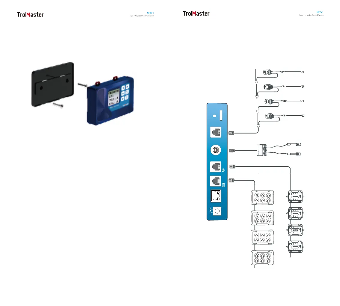
EasyManuals Logo

TrolMaster Aqua-X NFS-1 User Manual

TrolMaster Aqua-X NFS-1
19 pages
To Next Page IconTo Next Page
To Previous Page IconTo Previous Page
Page #4 background imageLoading...
Page #4 background image
INSTALLATION
Determine where to locate the main controller. The controller comes
with a simple to use DIN type bracket. Pull the 4 tabs outward to
release the bracket from the unit, mount the bracket to a wall or
surface, place the unit back on the bracket and press the 4 tabs back
in to lock the unit in place.
CONNECTIONS
DC
INTERNET
MICRO SD
SENSOR
BOARD
110V
CONTROL
24V
CONTROL
WATER
DETECTOR
SENSOR BOARD
pH
Sensor
EC/TEMP
Sensor
110V Control Boards
24V Control Boards
Water Detectors
06 07

Questions and Answers:

Question and Answer IconNeed help?

Do you have a question about the TrolMaster Aqua-X NFS-1 and is the answer not in the manual?

TrolMaster Aqua-X NFS-1 Specifications

Control Boards IconControl Boards
OA6-24 Control BoardMax. 5pcs per set
OA6-110 Control BoardMax. 5pcs per set
DSP-1 Program Device StationMax. 5pcs per set
Sensors IconSensors
AMP-2 Sensor BoardMax. 1pc per set
PCT-1 or PCT-2 EC/Temp SensorMax. 1pc per set
PPH-1 or PPH-2 pH SensorMax. 1pc per set
WD-1 Water DetectorMax. 30pcs per set
Alarm Setpoints IconAlarm Setpoints
pH Alarm Setpoint Range0~14
EC Alarm Setpoint Range0~5
Temp Alarm Setpoint Range32°- 122°F
pH Alarm Default Value5~7
EC Alarm Default Value1~2.5
Temp Alarm Default Value63°- 70°F
Connectivity IconConnectivity
Max Distance to Device to be connected1000 meters
Control Board Outputs24V Control Board (6 outputs each), 110V Control Board (6 outputs each), Program Device Station (1 output each), up to 30 outputs per set

Related product manuals