SETTING PAGE
2.9 EC
75.2 F
5.9 pH
Alarm Message
. pH Sensor Senso
03 : 57 01/25 2000
. EC Sensor Senso
03 : 57 01/25 2000
. Temp Sensor Senso
03 : 57 01/25 2000
110V
Board Board
24V
Alarm Setting
System Setting
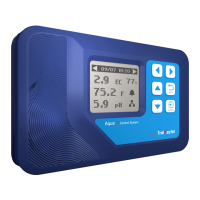
On the Main Menu page or Alarm Message page, press
ENTER
button to get access to the SETTING page. The LCD screen will
display 4 subjects (110V Board, 24V Board , Alarm Setting and System
Setting) as shown on above picture. You can press the respective
button (UP/DOWN/LEFT/RIGHT) to select the subject that you want
to adjust the setting.
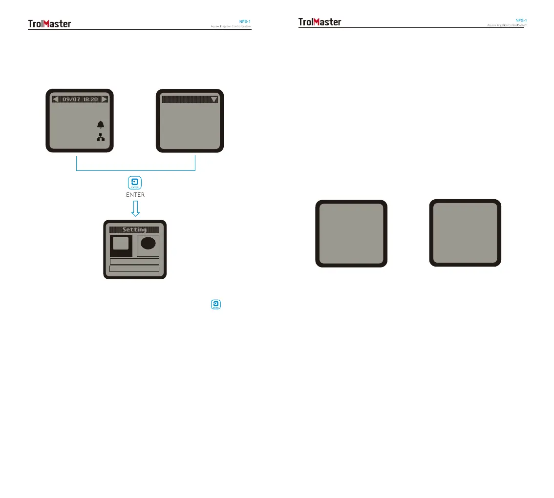
110V BOARD SETTING
When the RJ12 cable is not correctly connected to the corresponding
110V
CONTROL port or the 110V Control Board is not connected to
the power supply,
the LCD screen will show “No 110V Board Online”.
Please make sure the RJ12 cable is correctly connected and power on
the 110V Control Board. After power-on,
the Addressing LED indicator
will keep flashing every second. Then press the
ADDRESSING button
on the 110V Control Board, the LCD screen will display “110V Board A has
been added”. The first connected Control Board will be marked as “A”,
and the second one marked as “B”, the third as “C”, and so on.
No 110V Board
Online
110V Board A
has been added
Wrong Connection Correct Connection
On the SETTING page, press ENTER button to enter the 110V Control
Board list page. The connected Control Board(s) will be shown page to
page. User can press RIGHT button to select the 110V Control Board
(A, B, C…) for the setting change.
14 15
 Loading...