EasyManua.ls Logo

TrolMaster Aqua-X NFS-1 - User Manual

TrolMaster Aqua-X NFS-1
19 pages
Print Icon
To Next Page IconTo Next Page
Loading...
Aqua-X Controller

Questions and Answers

  • C
    Christine MckinneyAug 4, 2025
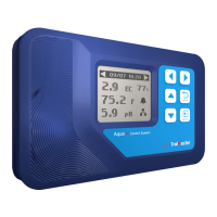
    What does it mean when the BELL icon is flashing on my TrolMaster Controller?
    • A
      Adam GayAug 4, 2025
      A flashing BELL icon on your TrolMaster Controller indicates an alarm state. This means that a temperature, pH, or EC value is outside the set range, or a water sensor alarm has been triggered.
  • S
    Sara WeberAug 10, 2025
    Why can't I add OA6-24, OA6-110, DSP-1, or WD-1 to my TrolMaster Aqua-X Controller?
    • J
      jreedAug 11, 2025
      There are several reasons why you might not be able to add these devices to your TrolMaster Aqua-X Controller. Ensure that you are using the correct input ports: the 24 CONTROL port for OA6-24, the 110V CONTROL port for OA-110 & DSP-1, and the WATER DETECTOR port for WD-1. Also, check that you haven't exceeded the maximum number of connectable devices: 30 for WD-1, and 5 each for the 24V or 110V Control Board & DSP-1.
  • E
    Elizabeth TaylorAug 19, 2025
    Why can't I add a new device to my TrolMaster Aqua-X NFS-1 Controller even though I have less than 5 of OA6-24, OA6-110 & DSP-1?
    • T
      Teresa MorenoAug 19, 2025
      After adding 5 devices (110V or 24V, DSP-1 belongs to 110V device), it is no longer possible to add any device with the same voltage. To add more devices, you need to perform a 'System Reset - Device Reset' to clear all device addresses. You must remove one or more devices with the same voltage before doing so.
  • R
    Rhonda WalkerAug 27, 2025
    Why are the setting parameters cleared on my TrolMaster Aqua-X NFS-1?
    • C
      Carlos GonzalezAug 27, 2025
      If an added board is offline and a new board is added in the same position, the setting parameters of that board and the setting parameters of its associated water sensor will be cleared.

Summary

Please Read First

Introduction to Aqua-X Controller

Key Facts for Aqua-X Controller

Aqua-X Controller Components

Installation Guide

Connecting the System

Further Connection Details

Controller Buttons Overview

Initial System Setup

Main Menu Navigation

Accessing the Setting Page

110 V Board Settings

Setting Schedules by Time

Configures irrigation schedules using time-based settings.

Setting Schedules by Recycle

Configures irrigation schedules using cycle-based repeat settings.

24 V Board Settings

Water Detector Settings

Leak Sensor Mode

Sets the water detector to operate in leak detection mode.

Output Assignment Mode

Assigns water detectors to specific control board outputs.

Alarm Settings Configuration

EC Alarm Setup

Sets the minimum and maximum values for EC alarms.

Temperature Alarm Setup

Sets the minimum and maximum values for temperature alarms.

pH Alarm Setup

Sets the minimum and maximum values for pH alarms.

System Settings

Temperature Format Selection

Selects the temperature display unit between Fahrenheit and Celsius.

Time and Date Configuration

Configures the current date and time for the system.

Serial Number and QR Code

Displays the device's QR code and unique serial number.

System Reset Options

Performs device reset, factory reset, or firmware/module updates.

Calibration Procedures

Guides the user through the EC and pH calibration procedures.

Emergency Stop Function

Activates an emergency stop for all connected devices.

Product Registration

Troubleshooting Common Issues

Technical Specifications

TrolMaster Aqua-X NFS-1 Specifications

Control Boards IconControl Boards
OA6-24 Control BoardMax. 5pcs per set
OA6-110 Control BoardMax. 5pcs per set
DSP-1 Program Device StationMax. 5pcs per set
Sensors IconSensors
AMP-2 Sensor BoardMax. 1pc per set
PCT-1 or PCT-2 EC/Temp SensorMax. 1pc per set
PPH-1 or PPH-2 pH SensorMax. 1pc per set
WD-1 Water DetectorMax. 30pcs per set
Alarm Setpoints IconAlarm Setpoints
pH Alarm Setpoint Range0~14
EC Alarm Setpoint Range0~5
Temp Alarm Setpoint Range32°- 122°F
pH Alarm Default Value5~7
EC Alarm Default Value1~2.5
Temp Alarm Default Value63°- 70°F
Connectivity IconConnectivity
Max Distance to Device to be connected1000 meters
Control Board Outputs24V Control Board (6 outputs each), 110V Control Board (6 outputs each), Program Device Station (1 output each), up to 30 outputs per set

Related product manuals