Trust Automation, Inc. TA333 High Power Linear Servo Amplifier
10-Apr-09 Page 11 of 38
1.9 Enable Input
The ENABLE input can be selected as active-high or active-low logic at SW1 position 1. (See table 4.8
)
The input must be pulled to logic low (ISO GND) or logic high (ISO +5) for the TA333 to operate. The
ENABLE line is pulled up internally to ISO +5. The TA333 provides an isolated +5V source at connector
J3 and J4 with a maximum draw of 100mA. If the application requires more current, the user must
supply an external 5V that must be referenced to the ISO ground connection.
The TA333 must not be enabled during power up.
If the drive is powered up when enabled, the drive
will not enable and will assert FAULT. The ENABLE input must then be cleared and re-asserted to
enable the drive.
Note: A minimum sinking capability (I
OL
) of 5mA is required.
Note: Logic low input minimum voltage (V
IL
) is 0.8V. Logic high input minimum voltage (V
IH
) is 2.0V with
a maximum on 5.2V.
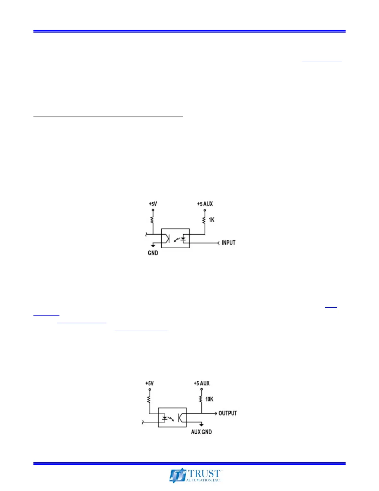
See circuit in the following figure:
Figure 1 – Enable Circuit
1.10 FAULT Output
The TA333 FAULT output is selectable as active-high or active-low logic, set at SW1 position 2. (See
table 4.8
) The TA333 will assert FAULT upon over-current or thermal overload based on the SOA
graph. (See section 2.4)
Past FAULT information is stored in internal memory and may be accessed at
the serial monitoring port. (See section 1.16)
Note: Logic output high minimum voltage (V
OH
) is 2.5V. Logic output low maximum voltage (V
OL
) is
0.8V.
See circuit in the following figure:
Figure 2 – Fault Circuit