Trust Automation, Inc. TA333 High Power Linear Servo Amplifier
10-Apr-09 Page 16 of 38
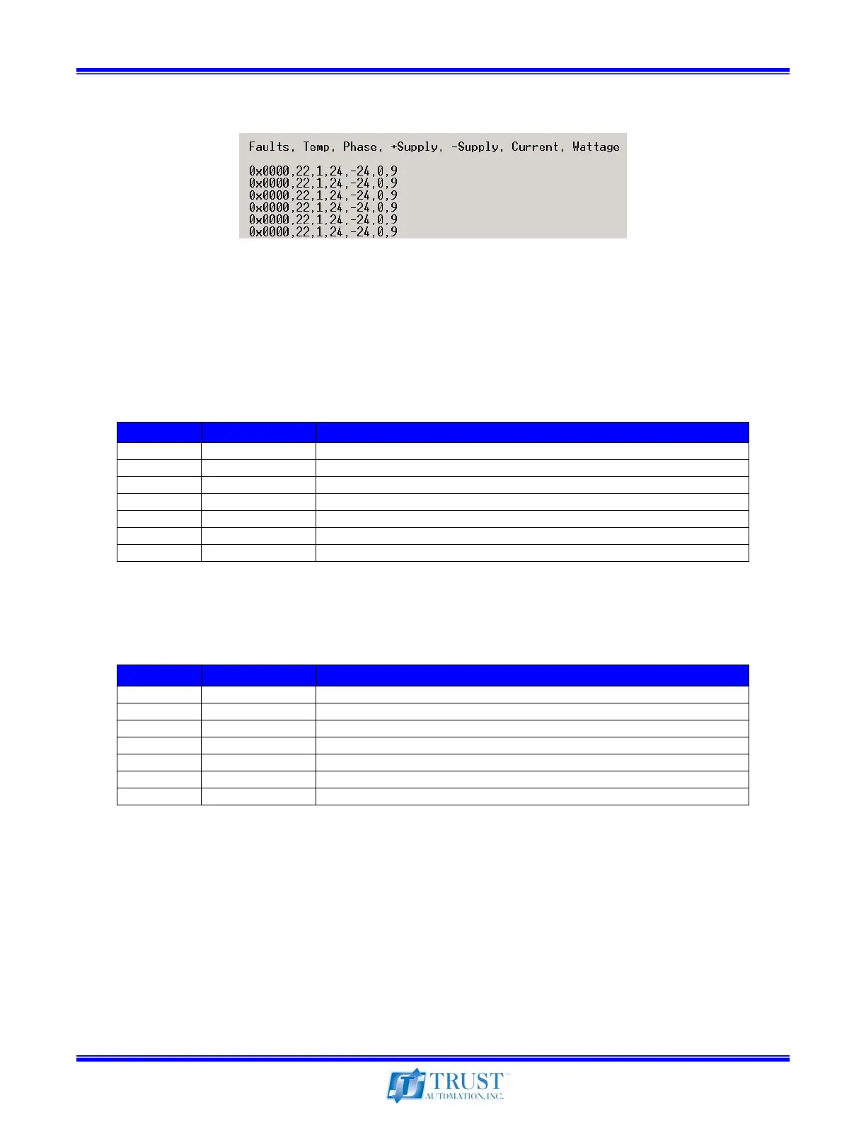
Once the TA333 is enabled, data will begin transmitting in the following format:
Figure 6 – Data Transmission Format, HyperTerminal
Figure 6 shows the drive set to brushless motor mode, no faults, heatsink at 22°C, positive supply at
24V and negative supply at 24V. There is less than 1A current flow and integer math has placed the
dissipation at 9W.
The data stream may be stopped by transmitting “s” followed by “Rtn.” The data stream will resume
upon sending the “s” + “Rtn” sequence again. Data layout is formatted as:
Data field Data Name Description
1 Fault Amp fault data (See fault chart)
2 Temp, Celsius Temperature of heat sink, SOA de-rated as temperature rises.
3 Phase Voltage The captured phase voltage
4 + Supply V Positive supply voltage
5 - Supply V Negative supply voltage
6 Phase Current The highest captured phase current
7 Wattage Amp dissipation wattage based on data gathered
Table 1 – Data Transmission Format
Faults are formatted as:
Table 2 – Fault Codes
Fault Name Description
0x0000 No Fault Operation Normal
0x0002 Temp Over temp fault at 70c, The TA333 will disable @ 90c
0x0001 Supply Under voltage @ 20V, Over voltage @ 105V
0x0004 Current Over current fault based on time limit and SOA
0x0008 Wattage Over continuous wattage limit based on time and SOA
0x0010 Peak Wattage Peak wattage limit based on time and SOA
0x0020 Enable Enable fault if drive is powered up in the enabled state