Trust Automation, Inc. TA333 High Power Linear Servo Amplifier
10-Apr-09 Page 24 of 38
4.0 Connector and Switch Information
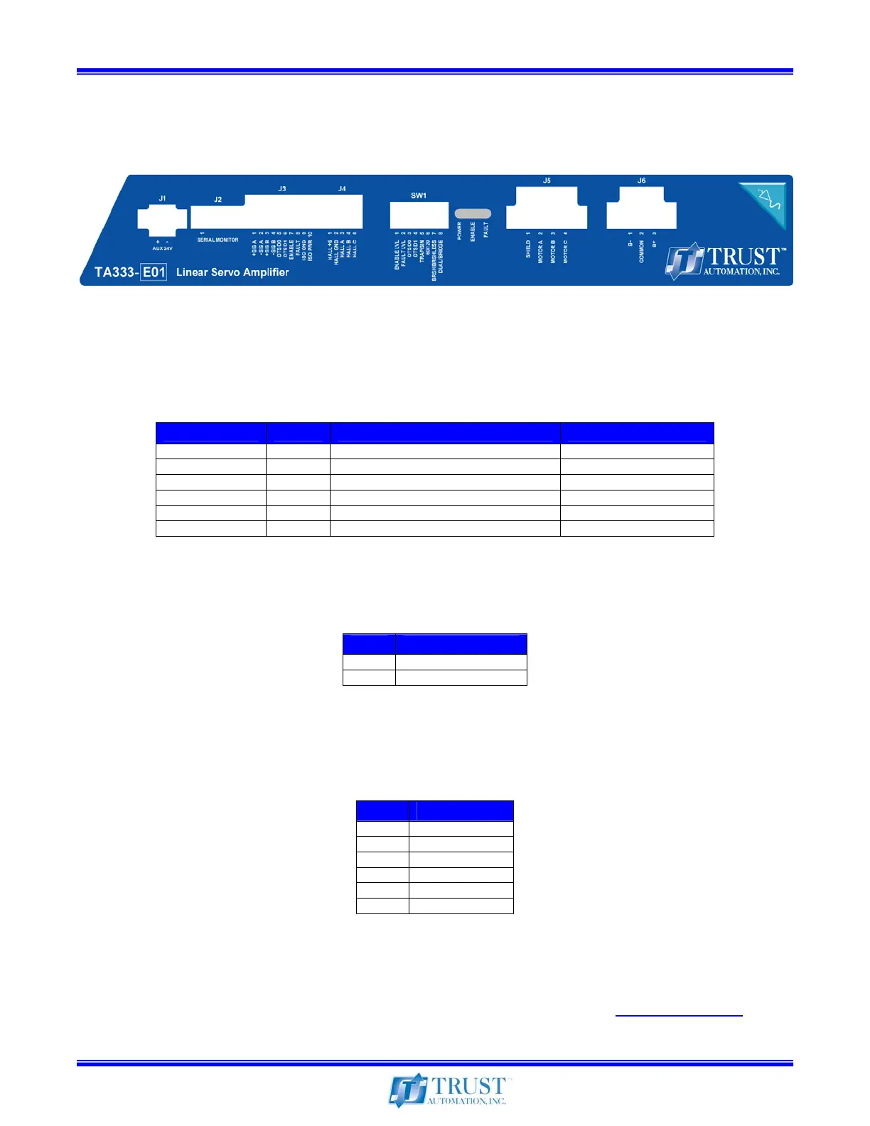
4.1 Front Panel Connector and Switch Layout
Figure 14 – TA333 Front Panel
4.2 Connector Types
Table 6 – Connector Types
4.3 J1 – External 24VDC Supply
Pin # Description
1 24V External Supply
2 Common (Isolated)
Table 7 – External 24VDC Supply Connector
4.4 J2 – Serial Monitoring Port
Pin # Description
1 ISO Gnd
2 CTS (Not used)
3 V
ISO
4 TXD
5 RXD
6 RTS (Not used)
Table 8 – Serial Monitoring Connector
J2 provides a TTL level serial port to monitor the operating conditions on the load and the internal
health of the TA333. The optional TTL Serial to USB cable provides a convenient conversion for
viewing the data with any terminal program such as Windows HyperTerminal. (See section 1.16)
Connector # # Pins Manufacturer & Part Number Description
J1 2 Phoenix 1827703 External 24VDC Supply
J2 6 FTDI P/N TTLUSB TTL to USB
J3 10 Wago P/N 733-110 Command Signals
J4 5 Wago P/N 733-105 Hall Sensors
J5 4 Phoenix 1825336 Motor Signal
J6 3 Phoenix 1777992 Motor Power