Trust Automation, Inc. TA333 High Power Linear Servo Amplifier
10-Apr-09 Page 25 of 38
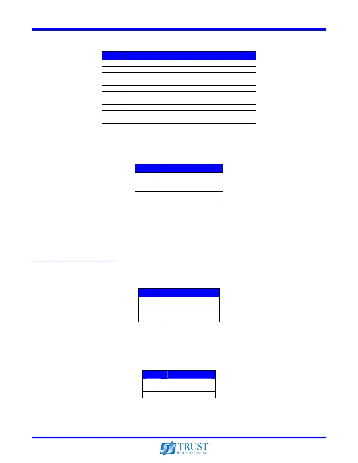
4.5 J3 – Command Signals
Pin # Description
1 Command Signal Input Phase A+
2 Command Signal Input Phase A-
3 Command Signal Input Phase B+
4 Command Signal Input Phase B-
5 Dynamic Transconductance Select Bit D0
6 Dynamic Transconductance Select Bit D1
7 ENABLE (Referenced to ISO Gnd)
8 FAULT (Referenced to ISO Gnd)
9 ISO Gnd
10 V
ISO
(Internal supplied +5V@ 100ma Optical Isolation)
Table 9 – Motor Command Signals Connector
4.6 J4 – Hall Sensor Input
Pin # Description
1 ISO +5 (20mA Maximum)
2 ISO Gnd)
3 Hall A
4 Hall B
5 Hall C
Table 10 – Hall Sensor Input Connector
Note: If the motor has differential Hall outputs, only connect the “+” Hall outputs to J4 and leave the “–”
Hall signals unconnected. (Do not tie to ground, the motor will be damaged.)
Note: If the Hall sensors require more than 20mA, an external +5V must be supplied.
(See application example 5.3)
4.7 J5 – Motor Signals
Pin # Description
1 Shield (tied to chassis)
2 Motor Phase A / U / R
3 Motor Phase B / V / S
4 Motor Phase C / W / T
Table 11 – Motor Signals Connector
Note: Phase A, B and C are the same as U, V and W or R, S and T found on most commercial motors.
4.8 J6 – Motor Power
Pin # Description
1 B- Supply
2 Common (Isolated)
3 B+ Supply
Table 12 – Motor Power Connector