Trust Automation, Inc. TA333 High Power Linear Servo Amplifier
10-Apr-09 Page 26 of 38
4.8 SW1 – Switch Settings
Switch # Function – (0 / Down / On) Function – (1 / Up / Off)
1 /ENABLE (drive enabled on low Input) ENABLE (drive enabled on high input)
2 /FAULT (FAULT low true output) FAULT (FAULT high true output)
3 Gain and DTS Settings See Following Chart for Function Selection
4 Gain and DTS Settings See Following Chart for Function Selection
5 Trapezoidal Commutation Sinusoidal Commutation
6 60° Hall Commutation 120° Hall Commutation
7 Brush type motor (or voice coil) Brushless type motor
8 Dual Brush type motor (unbridged) Single Bridged motor (bridged)
Table 13 – SW1 Settings
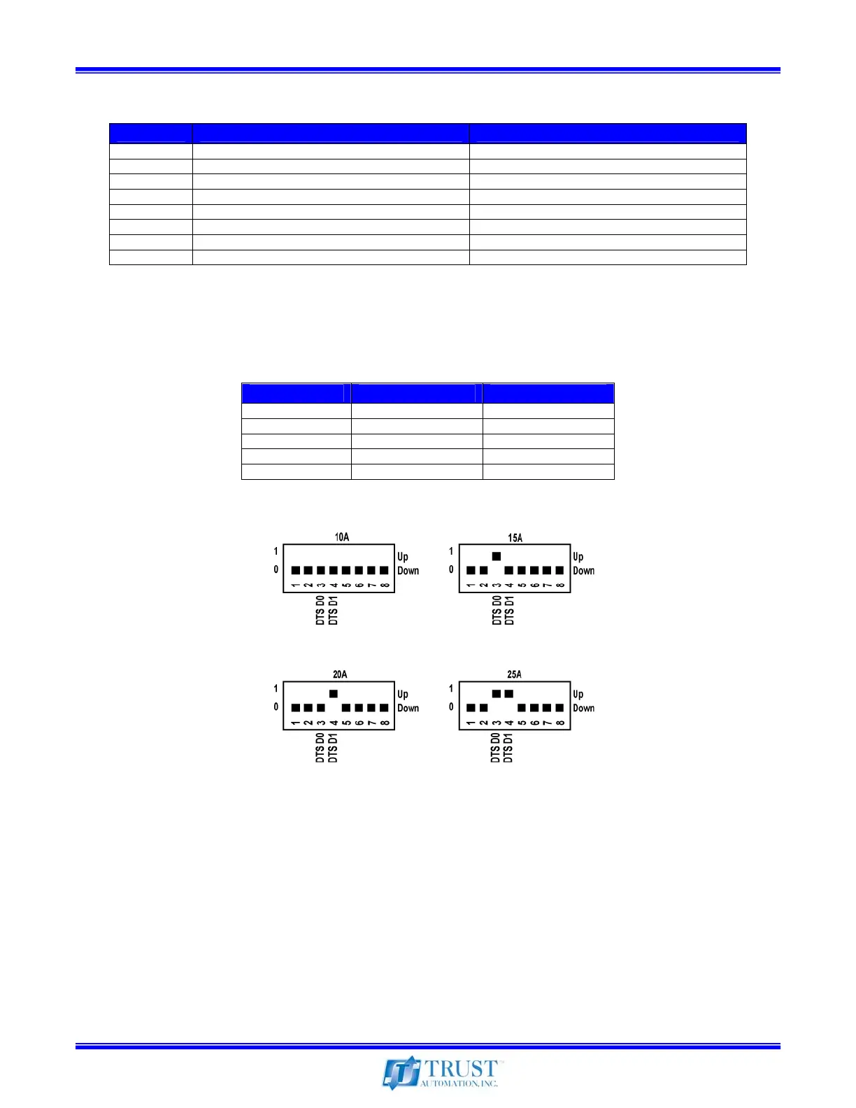
4.9 SW1 – Switch 3 and 4, Fixed Gain and DTS Settings
Setting SW1-3 (DTS D0) SW1-4 (DTS D1)
10Vin = 10A out
Down (0) Down (0)
10Vin = 15A out
Up (1) Down (0)
10Vin = 20A out
Down (0) Up (1)
10Vin = 25A out
Up (1) Up (1)
DTS Active
Up (1) Up (1)
Table 14 – Fixed Gain and DTS Switch Settings
Figure 15 – Fixed Gain and DTS Settings
(Note: “Down” is toward the heatsink, “Up” is away from the heatsink)