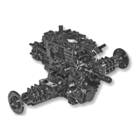
Tuff Torq K92 Hydrostatic Transaxle
Installing:
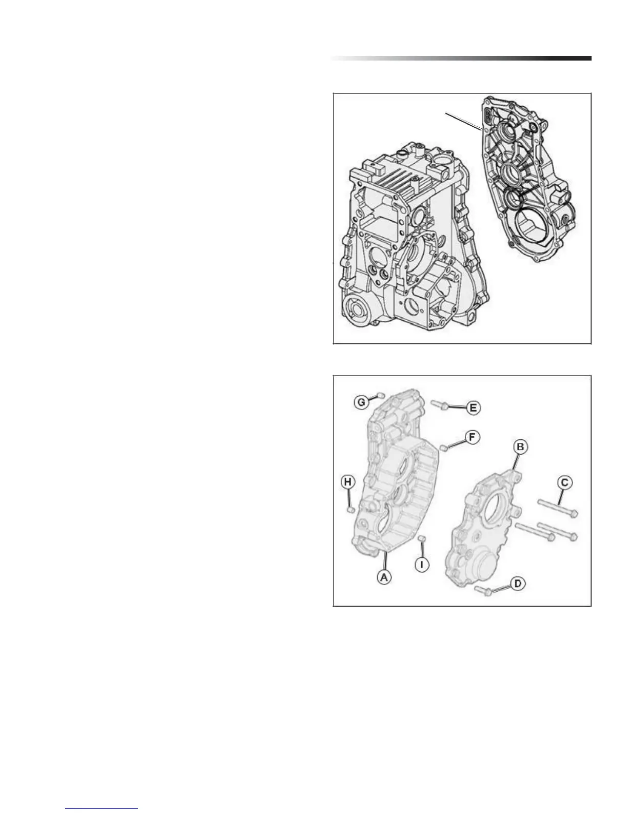
1. Clean mating surfaces of rear case and transaxle
case. Be sure threaded holes are clean. (Fig. 23)
2. Apply petroleum jelly to seal on shaft of PTO clutch
as-sembly (E). (Fig. 22)
3. Apply a bead of silicon sealant to rear case mating
sur-face. (Fig. 23)
IMPORTANT: Avoid damage! Be sure rear case is
aligned with transaxle case and installed within 4 mm
(1/8 in.) of case before tightening cap screws. Major
damage can occur to PTO case and/or transaxle case
if not installed properly be-fore tightening cap screws.
4. Carefully position the rear case (A) on the transaxle
and onto the lower dowel pin (H). Use a pry bar
between the PTO and frame to carefully move the
PTO approximately 1.5 mm (1/16-in.) to the right to
align the top of the case with the upper dowel pin
(G). Secure with (14) cap screws (E). (Fig. 24)
Rear Cover Cap Screw Torque Specifications:
• Used Transaxle Case . . . . . . . . . . . . . . . 25 N•m (18 lb-ft)
• New Transaxle Case. . . . . . . . . . . . . . . . 30 N•m (22 lb-ft)
• Internal Cap Screws. . . . . . . . . . . . . . . . 27 N•m (20 lb-ft)
5. Apply a bead of silicon sealant to PTO gear case (A)
mat-ing surface.
6. Carefully position the PTO cover (B) on the PTO case
(A). Align the top of the cover with the upper dowel pin
(F) and onto the lower dowel pin (I). Secure with (3)
cap screws (C) and (10) cap screws (D). (Fig. 24)
IMPORTANT: Avoid damage! Be sure cover is aligned
with transaxle case and installed within 4 mm (1/8 in.)
of case be-fore tightening cap screws. Major damage
can occur to cover and/or case if cover is not installed
properly before tightening cap screws.
Rear PTO Gear Case Cap Screw Torque Specifications:
• Used Transaxle Case . . . . . . . . . . . . . . 25 N•m (18 lb-ft)
• New Transaxle Case . . . . . . . . . . . . . . . 30 N•m (22 lb-ft)
8. Install transaxle drain plug. Refill transaxle with ap-
proximately 9.0L (9.5 qt) using ATF Type F as
required) to crosshatched area of dipstick.
9. Install any additional items removed prior to PTO.
Rear PTO Case
Mating Surface
Fig. 23, Rear PTO Cover and Transaxle Case Assembly
Fig. 24, Rear PTO Cover Assembly
13