21
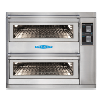
OVEN SYSTEMS
The Control System
This section contains information about the
following components:
- Control Board
-
Display
-
EMI Filter
-
F
uses
- High-limit Thermostat
- Keypad
- Power Supply, 24VDC
- Relay (K6 - Heaters)
- Relay (K7 - Conveyor Direction)
- Relay, Solid State
- RTD
- Smart Card Reader
- Speaker
- Thermostats - 120
º
F (Close on Rise)
- Wire Harness
This section also contains testing pr
ocedur
es for
the follo
wing components:
-
P
o
wer Supply - 24VDC
-
R
elay (K6 - H
eaters)
- Relay (K7 - Conveyor Direction)
- RTD
C
on
tr
ol Board
The contr
ol boar
d is po
wered by the 24 VDC
po
w
er supply
, and sends contr
ol voltage to each
relay. See schematics (pages 37-40). 24 VDC can
be measur
ed at the J9 connector, pins 19 and 8.
Displa
y
The v
acuum fluor
escent display is the primary
user interface, and is powered by the control
boar
d using 5
VDC. Its input voltage can be test-
ed at J7, pins 1 and 3 (page 39).
EMI Filter
The EMI filter helps suppr
ess the amount of RF
“noise” emitted by the oven, also filtering noise
fr
om entering the controls.
F
uses
The contr
ol circuit is ultimately protected by two
20-amp class CC fuses, which are in the line-
voltage circuit (incoming voltage). The fuses are
designed to blow in case of an over-current situa-
tion.
High-Limit Thermostat
The high limit thermostat is a 3-pole, manual
reset thermostat with a trip point of 572ºF
(300ºC). The thermostat interrupts power to the
heater elements.
Keypad
The keypad is an 11-key membrane switch.
P
ower Supply - 24VDC
The power supply converts line voltage to 24
VDC. Line voltage is connected to terminals L &
N. The output (24 VDC) is on terminals
“-V” and “+V”.
Testing Procedure
1. Check for line voltage at terminals L & N.
2.
If correct voltage is present, check output
(-V & +V
) for 24 VDC (with output wires
disconnected).
3. If voltage is present with output wires
disconnected and not pr
esent when the
wires are connected, inspect the wire
harness for damage or shorts (pages 37-40 for
schematics).
4. If wire harness is intact and undamaged,
the power supply is damaged or defective and
must be r
eplaced (page A-8).
Relays, K6 (Heaters) and K7 (Conveyor Direction)
The K6 and K7 relays are double pole, double
throw relays with a 24 VDC coil. The coil resist-
ance is 585 W and the contact rating is 30A at
240 VAC. When 24 VDC is applied to the coil,
the normally open contacts (7 & 4 or C & NO)
close, applying line v
oltage to energize the heaters
(K6) or reverse the conveyor direction (K7).

 Loading...