CPS6000 –48V Indoor/Outdoor Power Shelf
Issue 16 May 2006 62
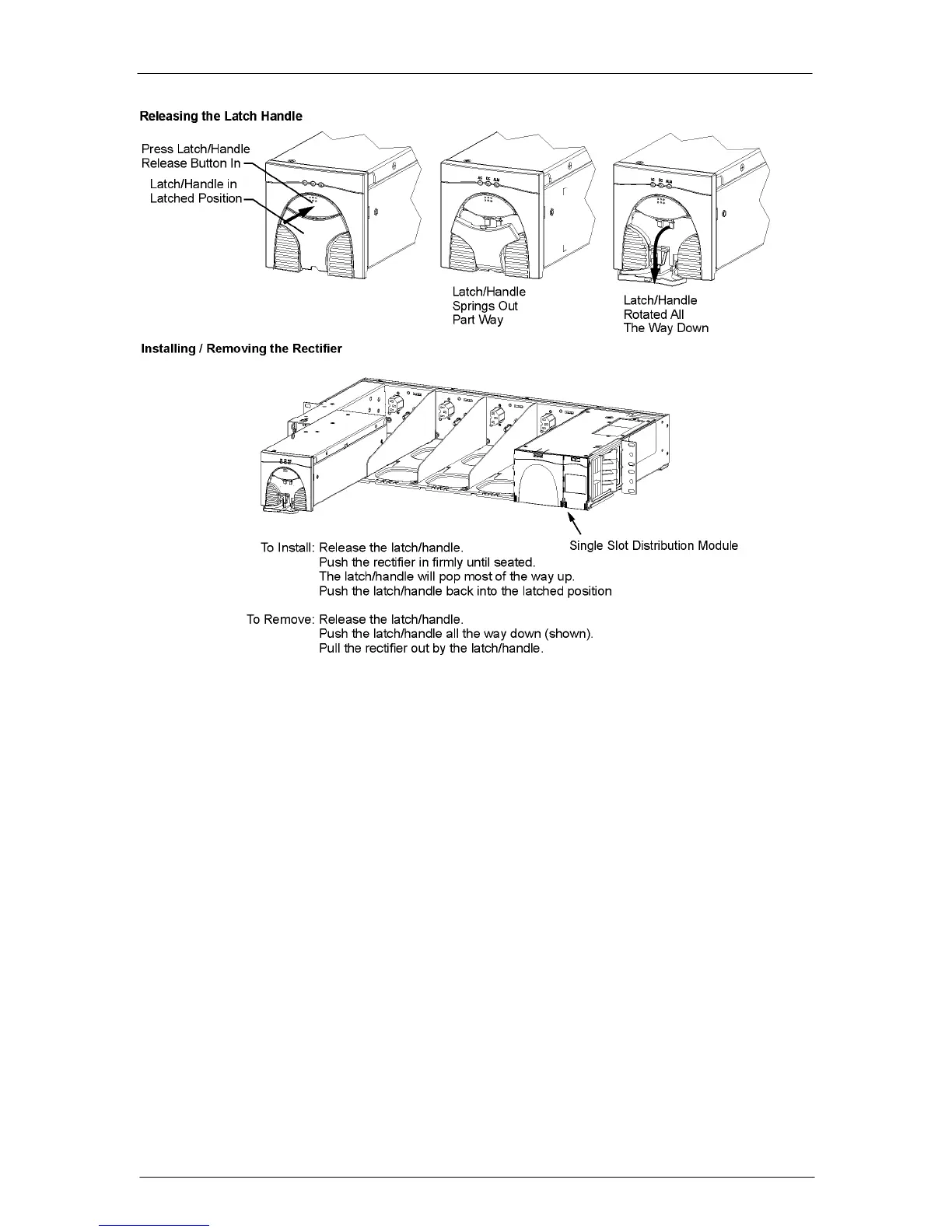
Figure 5-15: Rectifier Installation
Ringer Installation
Install the Ringer Chassis and Ringer Modules
This procedure is used to install ringer chassis’s and ringer modules in the CPS6000 shelf.
Figure 5-16 shows a shelf, Ringer chassis and a Distribution Module. Up to two Ringer
Chassis’s may be installed per shelf, one in each of the two right-most power slots to the left
of the Distribution Section. Each Ringer chassis accepts two ringer modules, a primary and a
spare. For redundant ringing, install both Primary and Spare Ringers in each Ringer Chassis.
The Ringer chassis and ringer modules are shipped separate.
Warning: Consider the Ring signal as hazardous voltage.
Warning: Ringer chassis’s and Ringer modules will be powered when installed in the shelf
when rectifiers and/or battery power is present.
Note: Ringer output connections are made after ringers are seated in the Ringer chassis.
Note: The primary and spare Ringer modules install facing opposite directions.