CPS6000 –48V Indoor/Outdoor Power Shelf
Issue 16 May 2006 45
Install the CPS6000 Shelf
Important Note
The following procedures are in order for a typical application. If the left side of the shelf will
be blocked after the shelf is installed in the framework, the following procedures should be
done before installing the shelf:
• Inter-Shelf Connections (multi-shelf installations only)
• AC Connections
• Office Alarm Cable
• Thermal Probe Connection
Leave a sufficient service loop on these cables.
Install the CPS6000 Shelf
Follow the steps in the table below to mount the CPS6000 shelf into a 19-inch or 23-inch
frame.
Step Action
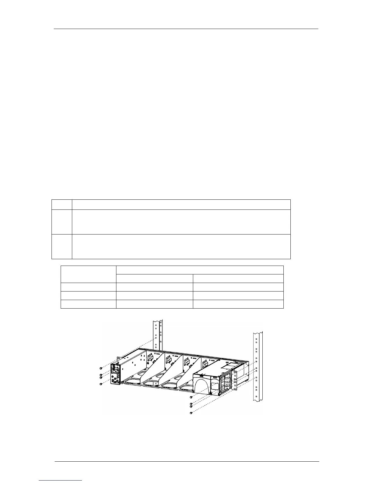
1. Locate the 2 mounting brackets, one on each side of the CPS shelf; align the
holes in the shelf-mounting bracket with the holes in the mounting frame. See
Figure 5-4.
2. Attach the CPS shelf to the frame using a minimum of four (two on each side)
of the 12-24 screws included in the supplied parts bag. Refer to the table
below for Torque Specifications.
Figure 5-4: CPS6000 Frame Mounting
Tor
ue
Hardware
Nm In-lbs.
Metric M5 4 35
12-24 4 35
Metric M6 7.3 65