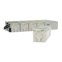
CPS6000 –48V Indoor/Outdoor Power Shelf
Issue 16 May 2006 89
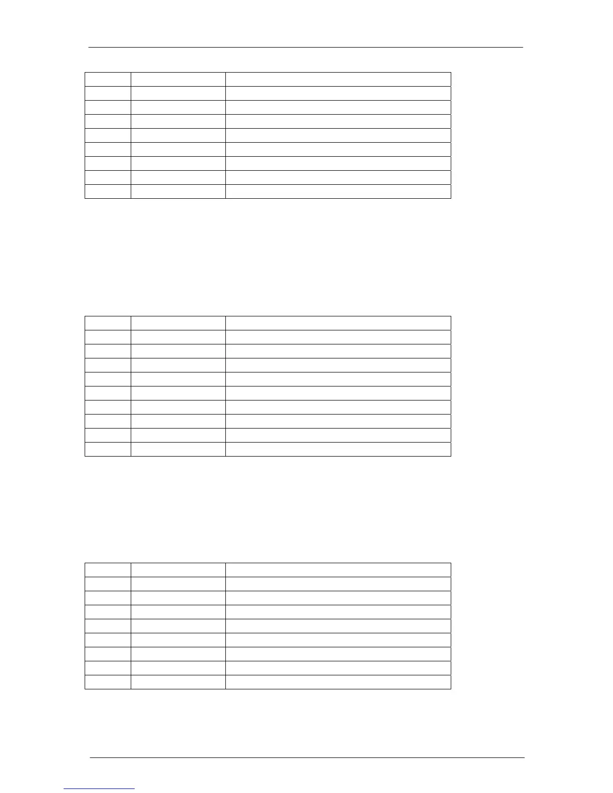
Pin Signal Description
1 RS-485 + RS485 GP communication bus
2 RS-485 - RS485 GP communication bus
3 SIG_RTN Protected signal return for RS485 and 1-wire
4
5 1-Wire 1-wire communication signal
6 +5V Protected +5V Power
7
8
Local RS232 Serial Port Connector
A DB-9 connector (J3) with a male housing and female pins supporting a local RS-232 port
with a subset of handshake signals is provided for local terminal access. This connector
provides an isolated RS-232 communication port for notebook computers and PCs.
The local port pin assignments should take the assignment as a Data Circuit-terminating
Equipment (DCE). This assignment is shown in the following table.
Pin Signal Description
1 RS-232 DCD *RS-232 Data Carrier Detect (output)
2 RS-232 TXD RS-232 Transmit (output)
3 RS-232 RXD RS-232 Receive (input)
4 RS-232 DSR RS-232 Data Set Ready (input)
5 RS-232 ISO GND RS-232 Isolated Ground
6 RS-232 DTR *RS-232 Data Terminal Ready (output)
7 RS-232 CTS RS-232 Clear To Send (input)
8 RS-232 RTS RS-232 Request To Send (output)
9 NC No Connect
* These signals are not necessary for supporting a local port connection.
LAN Connection (Ethernet)
A standard integrated RJ-45 receptacle (P6) is provided on the QS841A for connecting to an
appropriate 10/100 Base-T LAN. P6 is shielded with the shield being tied to chassis. This
connector is accessible when the controller is inserted in the shelf. The signals and pin
assignments for this interface follow industry standard and are shown in the following table:
Pin Signal Description
1 TX+ Tranceive Data+
2 TX- Tranceive Data-
3 RX+ Receive Data+
4 n/c Not connected
5 n/c Not connected
6 RX- Receive Data-
7 n/c Not connected
8 n/c Not connected