SARA-G450 - System integration manual
UBX-18046432 - R08 System description Page 31 of 143
C1-Public
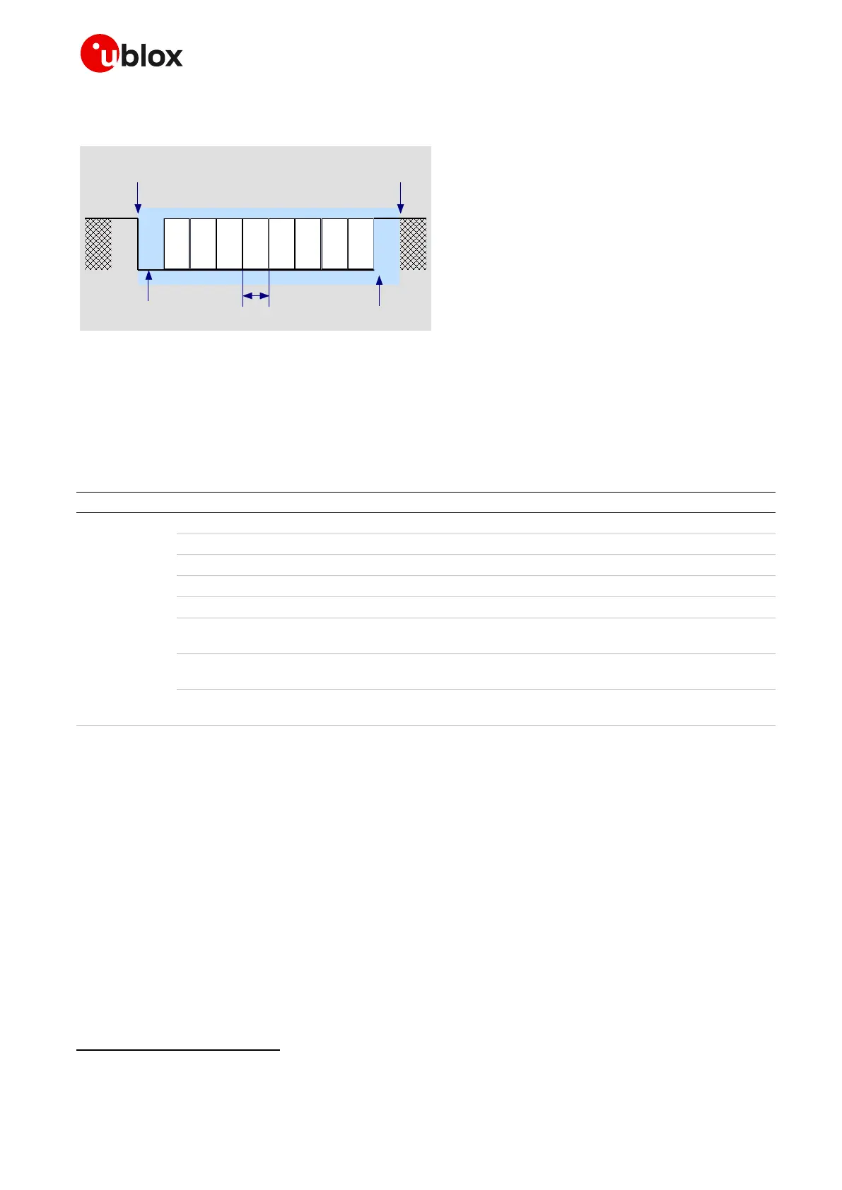
Figure 14 describes the 8N1 frame format, which is the default configuration.
D0 D1 D2 D3 D4 D5 D6 D7
Start of 1-Byte
transfer
Start Bit
(Always 0)
Possible Start of
next transfer
Stop Bit
(Always 1)
t
bit
= 1/(Baudrate)
Normal Transfer, 8N1
Figure 14: Description of UART default frame format (8N1) with fixed baud rate
1.9.1.2 UART AT interface configuration
The UART interface of SARA-G450 modules is available as an AT command interface with the default
configuration described in Table 8 (for more details and information about further settings, see the
u-blox AT commands manual [11]).
AT command mode is enabled by default on the UART physical interface
One-shot automatic baud-rate detection enabled by default
Frame format 8N1 enabled by default
HW flow control enabled by default
DSR line set ON in data mode
8
and set OFF in command mode
8
Upon an ON-to-OFF transition of DTR, the DCE enters online command mode
8
and issues an OK result code
Circuit 109 changes in accordance with the Carrier detect status; ON if the
Carrier is detected, OFF otherwise
Multiplexing mode is disabled by default and it can be enabled by AT+CMUX
command.
Table 8: Default UART AT interface configuration
1.9.1.3 UART signal behavior
At the module switch-on, before the UART interface initialization (as described in the power-on
sequence detailed in Figure 12), each pin is first tri-stated and then is set to its related internal reset
state
. At the end of the boot sequence, the UART interface is initialized, the module is by default in
active mode, and the UART interface is enabled as AT commands interface.
The configuration and the behavior of the UART signals after the boot sequence are described below.
See section 1.4 for definition and description of module operating modes referred to in this section.
RXD signal behavior
The module data output line (RXD) is set by default to the OFF state (high level) at UART initialization.
The module holds RXD in the OFF state until the module does not transmit some data.
See the u-blox AT Commands Manual [11] for the definition of command mode, data mode, and online command mode.
See the pin description table in the SARA-G450 data sheet [1].

 Loading...