Chapter 3: Architecture
20
Architecture
This chapter describes the functional operation of the PowerDAQ
AO boards.
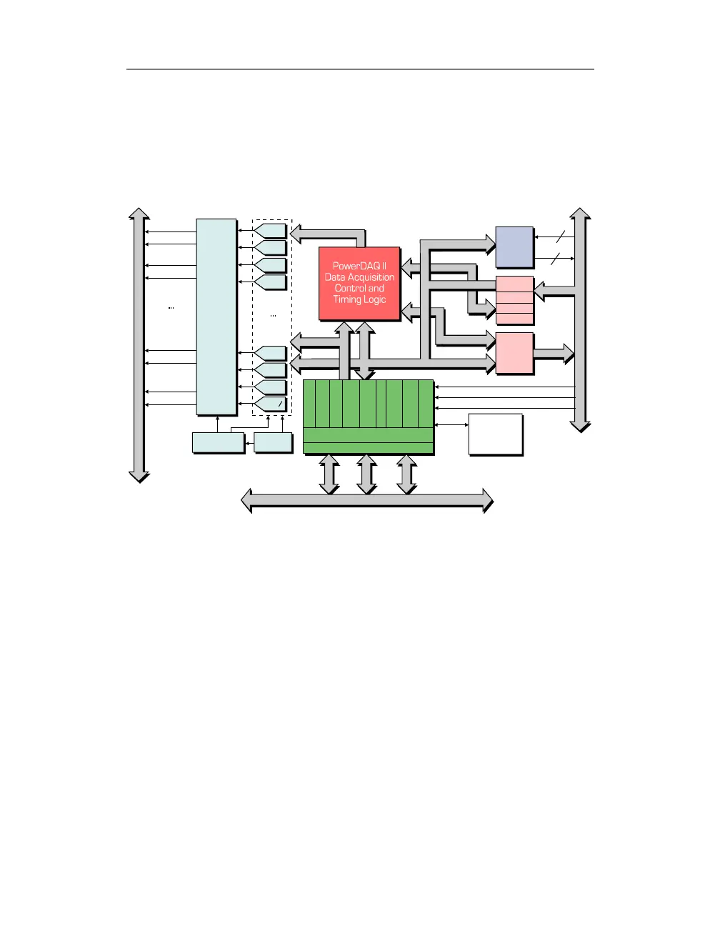
Figure 4: Block Diagram of the PowerDAQ PD2-AO boards
Functional Overview
Although there are some functional differences between the
PD2-AO and PDXI-AO boards they all utilize the same
PowerDAQ software, which significantly simplifies the
software development process.
Configur ation
& Calibr at ion
EEPROM
DAC1
DAC0
DAC2 9
DAC28
DAC3
DAC2
DAC3 1
DAC3 0
Volt age
Reference
AOut Calibrat ion
DACs
A
n
a
l
o
g
O
u
t
p
u
t
A
m
p
l
i
f
i
e
r
s
E
x
t
e
r
n
a
l
A
n
a
l
o
g
O
u
t
p
u
t
C
o
n
n
e
c
t
o
r
(
J
1
)
IRQA
AOUT0
AOUT0 SENSE
AOUT1
AOUT3 1
AOUT3 0
AOUT1 SENSE
A OUT3 1 SENSE
A OUT3 0 SENSE
IRQB
IRQC
DIn Contr ol
DOut Contr ol
Cloc k
Out
3
3
(8 )
I
n
t
e
r
n
a
l
D
i
g
i
t
a
l
I
/
O
C
o
n
n
e
c
t
o
r
J
2
(8 )
Local Dat a Bus
A
d
d
r
e
s
s
AOut Contr ol
Bus Master PCI Interface
Motorola 66MHz DSP 56301
E
S
S
I
A
O
u
t
F
I
F
O
A
O
u
t
C
l
o
c
k
6
C
h
a
n
n
e
l
D
M
A
1
2
k
P
r
o
g
r
a
m
R
A
M
1
2
k
D
a
t
a
R
A
M
B
o
o
t
s
t
r
a
p
R
O
M
U
s
e
r
C
l
o
c
k
U
s
e
r
C
l
o
c
k
C
o
n
t
r
o
l
A
d
d
r
e
s
s
D
a
t
a
32 Bit PCI Bus
User
Count er
Timer
3x24-bit
Digit al
Input
Buffer
Latch
Interrupt
Digit al
Out put
(Driver)
 Loading...