Chapter 5: Interconnections
4
The compatible pin out was used for the PD2-AO-8[16][32] and PD2-
MF(S) J1 connector to provide the ability to use common accessories.
For the details see conversion table in Appendix B. Note, that on PD2-
AO-8[16] AOUT16..31 and AOUT16..31 SENSE are connected to the
ground.
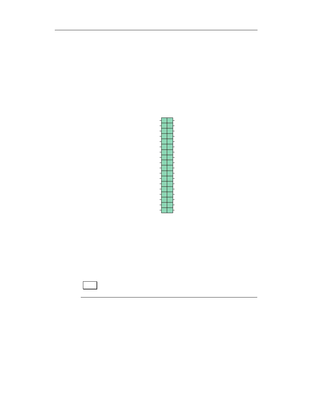
PD2-AO J2 DIO/Counter/Timers/IRQx
Connector
Figure 9: Connector pin assignment for the J2
J1-J2 Connection Example
The example below shows how to connect PD2-AO board to
the PD2-AO-STP screw terminal.
Note For the PD2-AO-8[16] board lines OUT16-OUT31 and
OUT16S-OUT32S are tied to the analog ground.
3
15
1
5
17
27
7
19
29
9
21
31
11
23
33
13
25
35
DGND
TM R0
DGND
DGND
TM R1
DIN0
DIN1
DIN2
DIN3
DIN4
DIN5
DIN6
DIN7
IRQA
IRQB
IRQC
DGND
DGND
DGND
TM R2
DGND
DGND
+5 VPJ 2
DGND
DOUT0
DOUT1
DOUT2
DOUT3
DOUT4
DOUT5
DOUT6
DOUT7
DGND
DGND
DGND
DGND
2
4
16
6
18
28
8
20
30
10
22
32
12
24
34
14
26
36
 Loading...