Chapter 5: Interconnections
41
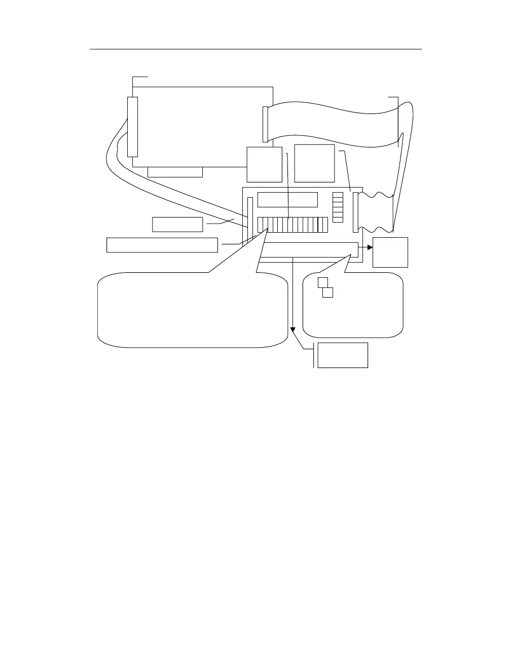
Figure 10: Configuring the PD2-AO-STP with PD2-AO-8[16][32]
PowerDAQ II Analog Output Board
(8/16/32 Channels)
Channels 0-15 and digital lines
Channels 16-31
PD-CBL-37
PD-AO-STP-32
Screw Terminal
IRQx and
TMRx
termination
umpers
Local
/Remote
Sense
umpers
AOUTx
SNSx
AOUTx – channel x output
SNSx – channel x sense line
or AGND (see jumpers JP1-
Jumpers JP1-JP32 defines the sense configuration for the
channels 0..31 respectively. When shunts installed at
locations B-C the channel is configured to remote sense
and SNSx terminal used to connect this line to the remote
equipment. If shunts are installed at A-B and C-D locations
the channel is configured to local sense (at screw terminal)
and SNSx terminal for the selected channel connected to
the AGND
To the servo-
motors, etc.
To/from
Digital
sensors
PD-CBL-96
 Loading...