36
Where the copper tube is protected by an insulation grip, the leak can be detected from both ends of each individual grip.
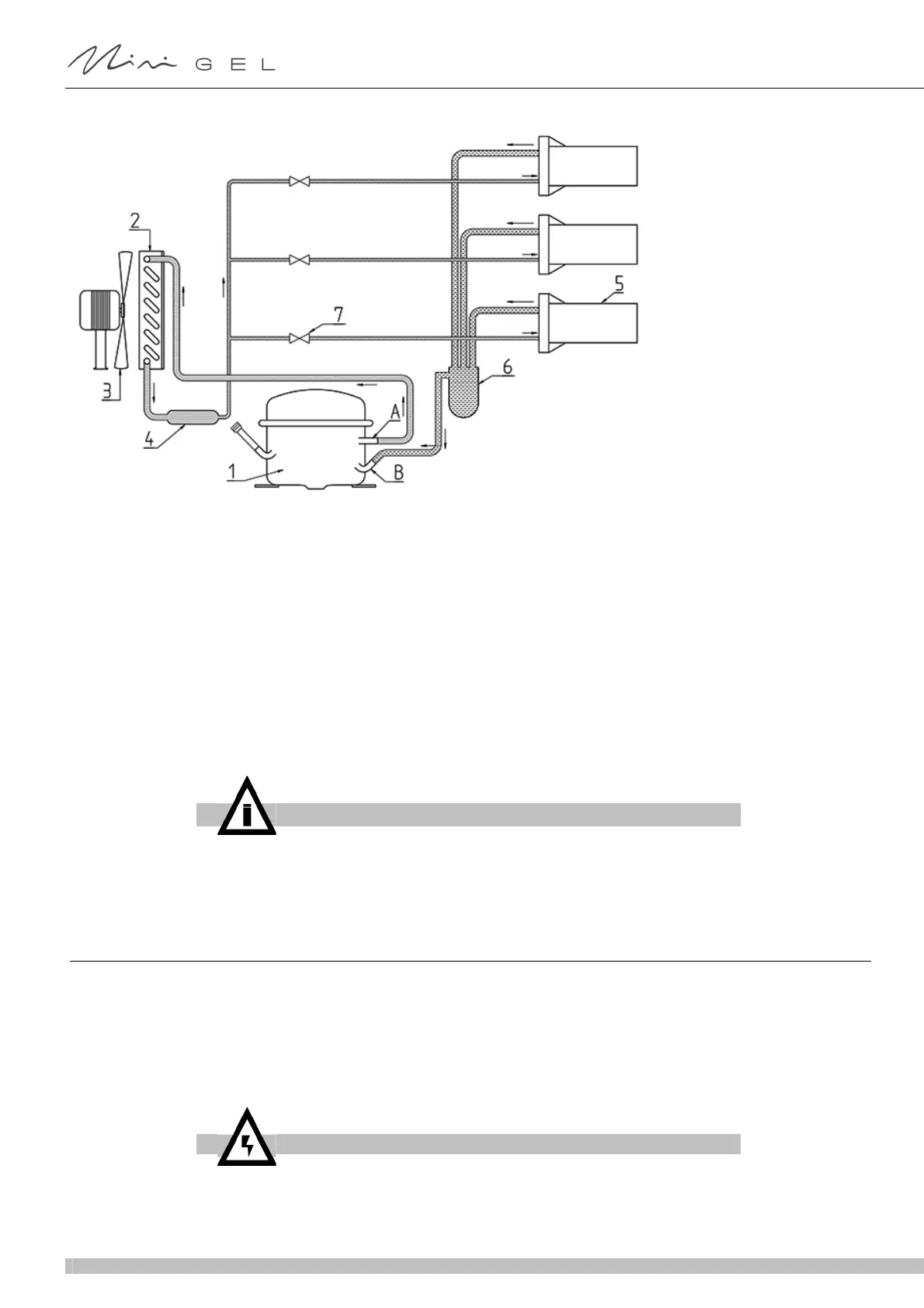
figure 3
Referring to figure 3, proceed as follows:
1 Begin the inspection at the “High Pressure” zone (discharge) of the compressor. Check around the seals.
2 Follow the copper pipes to the condenser and check the sealed connections at the condenser entrance and exit.
3 Also check the curves of the pipes on both sides of the condenser.
4 Follow the copper pipes to the evaporator, checking around the sealed connections on the dehydrator filter and the
electrovalves.
5 Disassemble the geared motors and check the evaporator capillary tube entry and the suction line outlet.
6 Check the copper pipes up to the compressor.
7 Inspect the “Low Pressure” zone of the compressor, checking the connections on the suction and inlet pipes.
8 Once the leak has been identified, seal it and charge with gas according to the instructions below.
12. 2 HOW TO EMPTY THE CIRCUIT
1 Remove all the machine’s panels.
2 Remove the cap from the “Charge” pipe valve on the compressor.
3 Connect the compressor “Charge” tube to the “Low” filling unit on the “pressure Gauge” (see figure).
4 Connect the "VAC” filling unit on the pressure gauge to an appropriate and approved gas collection device.
5 Open the “Low” and “VAC” valves and collect the gas.
A High pressure (discharge)
B Low pressure (suction)
1 Compressor
2 Condenser
3 Fan
4 Filter
5 Evaporator
6 Accumulator
7 Solenoid valve
IMPORTANT
Incorrect adjustment of the Production Parameters may compromise the opera-
tion of the machine.
WARNING
The refrigerant gas may be highly acidic and toxic.
 Loading...