38
To start the calibration:
1. Go to System g Maintenance g Calibration g Calibrate XY offset.
2. The Ultimaker 3 will now print a grid structure on the build plate. Wait until it is finished.
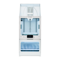
3. Once the Ultimaker 3 has cooled down, remove the glass plate from the printer and place it on the XY calibration
sheet. Ensure the printed grid it is exactly placed on the two rectangles on the sheet.
4. Find the aligned lines on the printed X grid and look which number belongs to these lines. Enter this number as
the X offset value on your Ultimaker 3.
5. Find the aligned lines on the printed Y grid and look which number belongs to these lines. Enter this number as
the Y offset value on your Ultimaker 3.
It is important that the printed XY offset print adheres well to the build plate and shows no signs of under
extrusion. If it does, it is recommended to re-do the calibration print.
Lift switch calibration
The switch bay is what enables the lifting and lowering of the second print core. For successful dual extrusion prints, it is
important that the switching functions well. The lift switch is already calibrated when the Ultimaker 3 is shipped, but the
calibration can also be done manually.
To perform the swith bay calibration:
1. Go to System g Maintenance g Calibration g Calibrate lift switch.
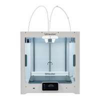
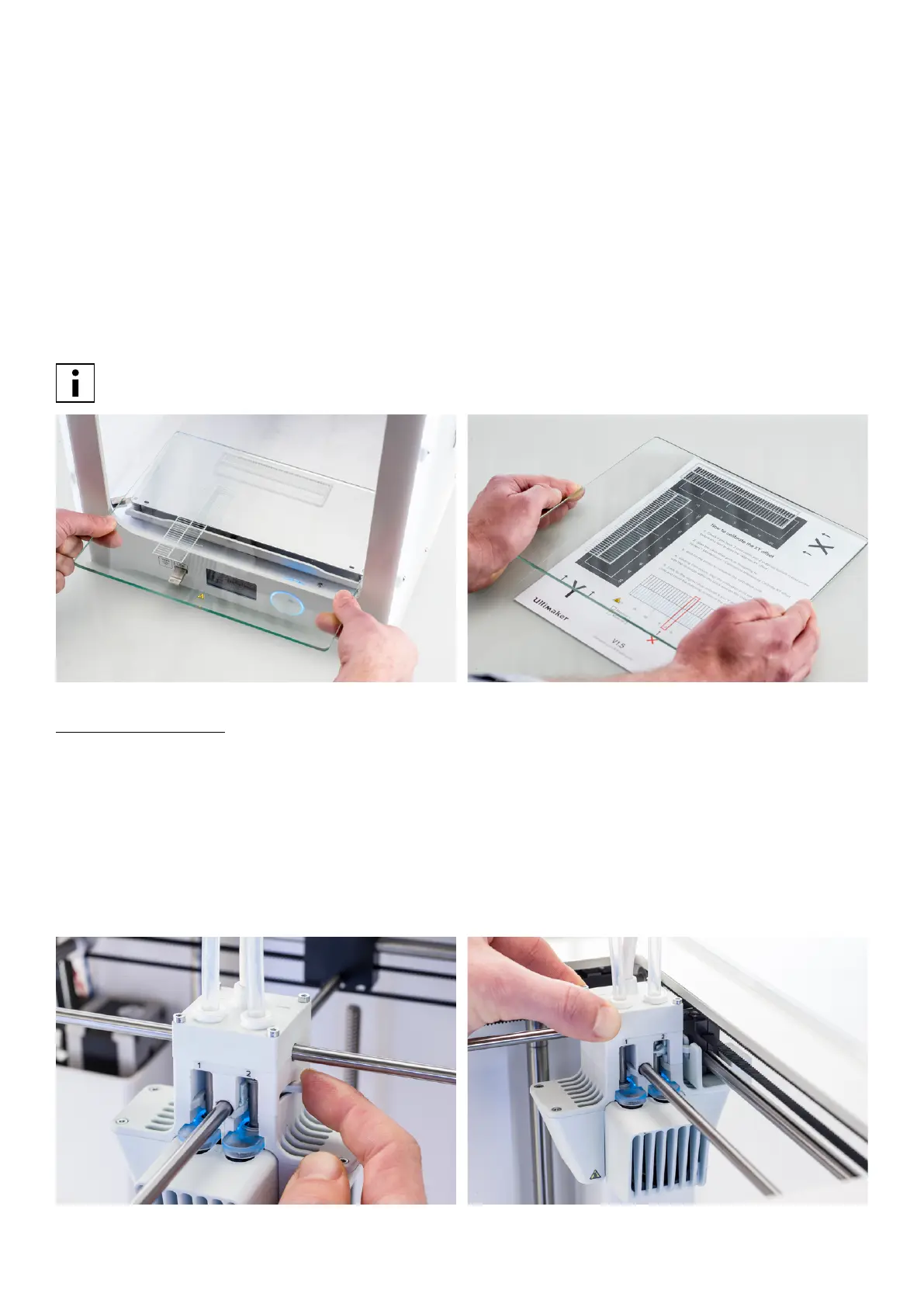
2. Move the lift switch on the side of the print head to point towards you.
3. Move the print head so that the lift switch fits in the switching bay.
4. Wait for the print head to go to the home position and test the lift switch.
5. Did the lift switch lower and raise the print core? If so, press “yes” to complete the calibration. If not, select “no” to
perform the calibration again.