DC Power Supply [DPG-30R & DPG-MC60R, DPG-MC120R, DPG-MC240R]
11
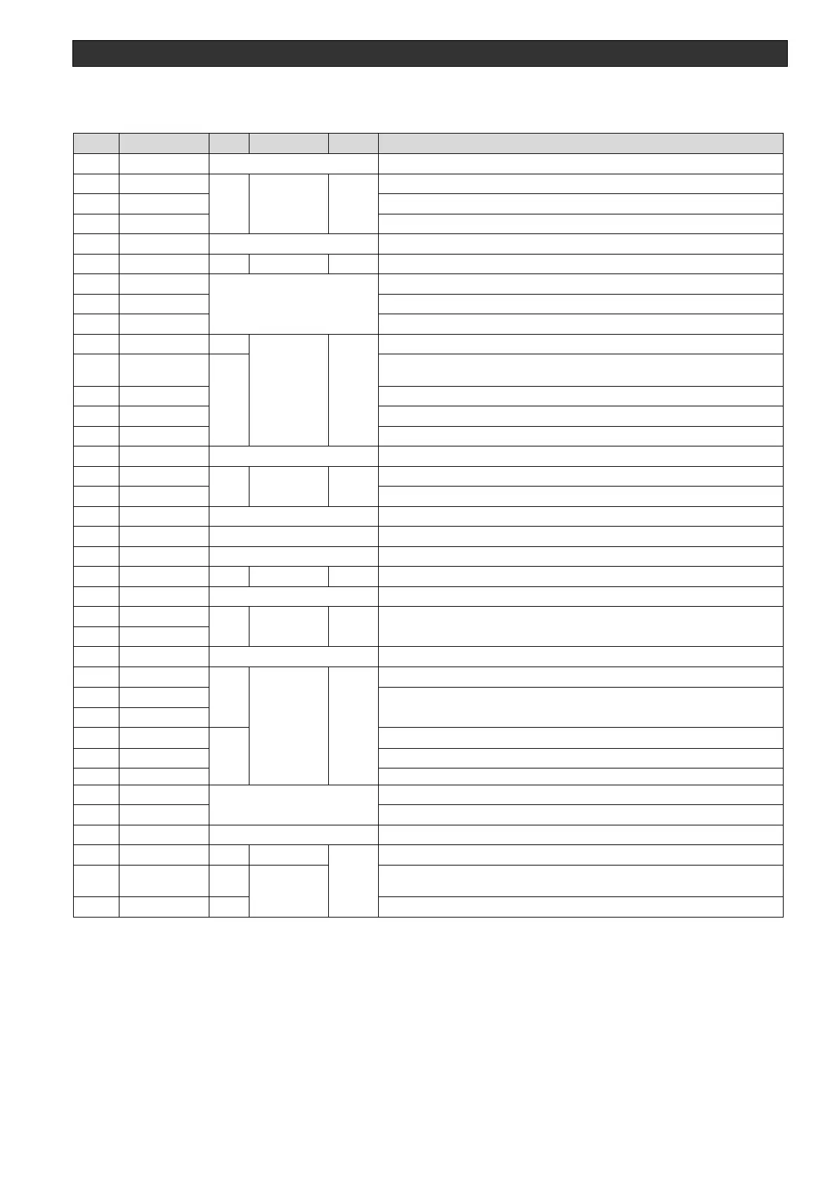
• When only the power supply is connected
Table 2-6 External control terminal pin assignments when only the power supply is connected
User interface analog signal common return
DC unit output voltage monitor signal *1
DC unit output current monitor signal *2
DC unit output power monitor signal *3
User Interface analog signal common return
ARC DELAY TIME setting on/off, on at low level
At low level, turns on DPG-30R output
Low level output when capable of output operation (low level also when
operating)
Low level output during output operation
Low level output while the DC unit is performing output at the set value
Low level output while an error is detected on the DC unit
Low level output between 32 us during hard arc detection on the DC unit
Low level output between 32 us during micro arc detection on the DC unit
User interface digital signal common return
User interface LEVEL signal common return
DC unit output setting voltage (0 to 10 V) *4
User interface analog signal common return
Sets the arc level by combination
150 V, 120 V, 90 V, 60 V, see 2-6-4
User interface digital signal common return
DC unit error reset (low active)
Changes the control mode by combination: constant power, constant
current, constant voltage.See 2-6-5
User interface digital signal common return
Apply 24 V from outside. 200mA or more
When the DC power supply panels are closed, output cable connected
,and pin 37 INTERLOCK is on, low level output
At low level, interlock OK
0 to 1500 V for voltage level output 0 to 10 V.
changes by the number of power supplies.see Table 4-1
changes by the number of power supplies.see Table 4-1
During P control:becomes the corresponding system power for a output setting voltage level 0 to 10 V
During I control: becomes the corresponding system power for a output setting voltage level 0 to 10 V
During V control: becomes the corresponding system power for a output setting voltage level 0 to 10 V