DC Power Supply [DPG-30R & DPG-MC60R, DPG-MC120R, DPG-MC240R]
21
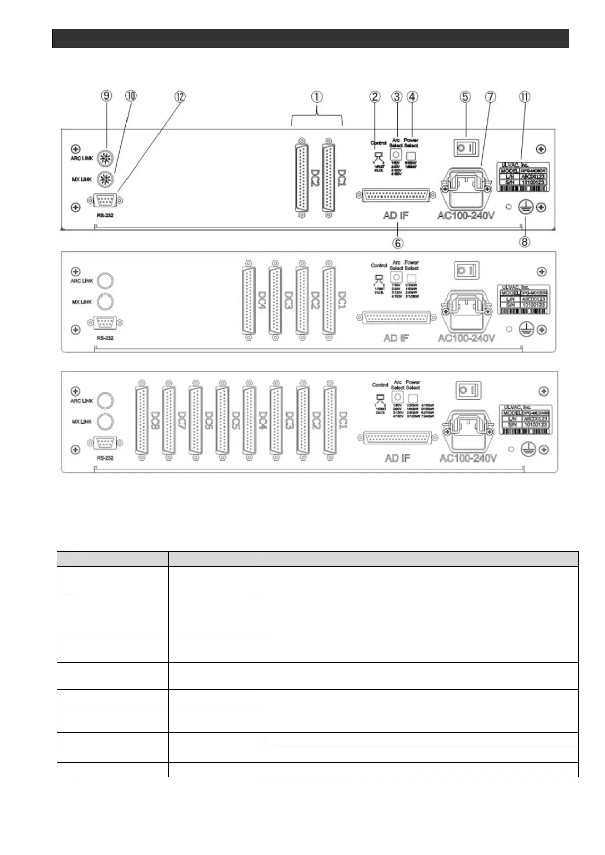
Rear panel
Figure 3-5 Controller rear panel (Top: MC-60R,Middle: MC-120R, bottom: MC240R)
Table 3-3 Controller rear names and functions
D-sub 37-pin
connector (male)
Communicates signals with the DC power supplies.
LOCAL/REMOTE
Selection switch
Switches between LOCAL and REMOTE control.
1. RMT side: REMOTE control
2. LCL side: LOCAL control
ARC LEVEL
selection switch
ARC LEVEL setting switch (1=60 V, 2=90 V, 3=120 V, 4=150 V)
Only enabled during LOCAL
System rated power setting switch (0=30 kW to 7=240 kW)
Turns the controller's power supply on and off.
D-sub 37-pin
connector (female)
Communicates signals with the external control device.
Chassis ground terminal.*2
Signal for high-speed ARC counters is outputted.