10
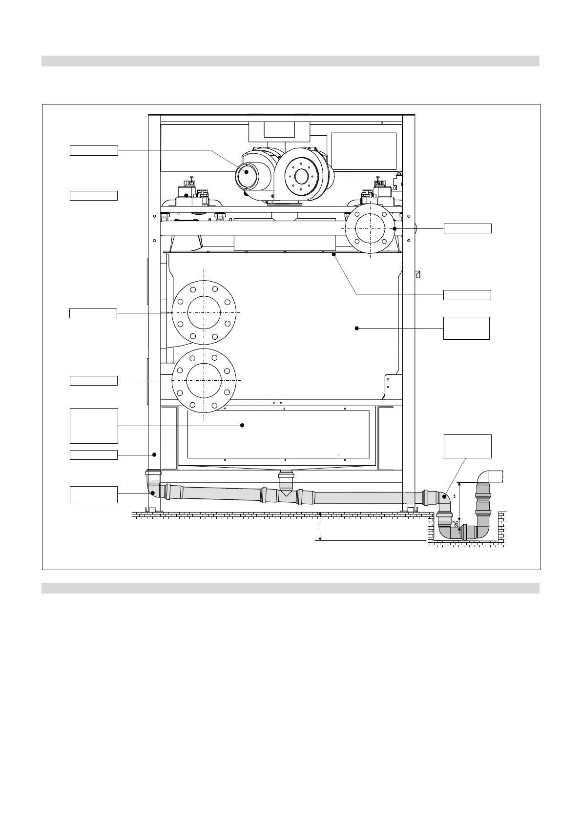
fig. 2
1.4 - SIDE VIEW WITH MAIN COMPONENTS
2.1 - COMPOSITION OF THE
SUPPLY
- Boiler body made of sections of alumi-
nium/magnesium/silicium alloy (5 to 8)
- Premix stainless-steel burner (4 to 7)
- Premixing chamber (8 to 14) with bu-
ilt-in non return valve
- Modulating fan (4 to 7) with air pres-
sure switch control
- Gas valve (2 for each module – from 8
to 14) with separated flame control
device SATRONIC (from 4 to 7)
- NTC sensors for local temperature con-
trol on each boiler section (5 to 8)
- NTC sensor for global flow manifold
temperature
- NTC sensor for global return mani-
fold temperature
- High Limit thermostat on each boiler
section (5 to 8)
- Automatic air vent on the flow mani-
fold
- Boiler draining/filling tap on return
manifold
- Minimum gas pressure switch on gas
manifold
- Condensate collecting tray
- Plastic pipe (1m) and fittings for con-
densate evacuation Ø40
- Smoke chamber terminal, with flue soc-
ket:
Ø 250 mm for models 360 and 450
Ø 300 mm for models 540 and 630
- Integral painted steel casing
- Modulation and control PCB (MBD)
with PC interface
- AM-4 PCB for DHW production and
outdoor temperature sensor
- Supplementary PCB type AM-5 (1 x
mod. 360; 2 x mod. 450 and mod. 540;
3 x mod. 630)
- Electronic card for interface
- Outdoor sensor (into the smoke cham-
ber)
150
FAN
GAS VALVE
GAS PIPE
BURNER
ALUMINIUM/
SILICON HEAT
EXCHANGER
CONDENSATE
DRAIN
SIPHON
CONDENSATE
COLLECTING
TRAY-
SMOKE
MANIFOLD
FILLING-UP
ELBOW
C.H. RETURN
C.H. FLOW
Min. Depth 100 mm
BOILER FRAME