24
2.6 - ELECTRIC
CONNECTIONS
The MODULEX electrical connections
are defined in the chapter “Wiring dia-
gram” (paragraph 2.6.1).
For electrical features see appliance data
plate.
The boiler installation needs a supply
of 230 V – 50 Hz – single phase, and
must be workmanlike performed, as fore-
seen by the local and international elec-
trical rules in force and without the utili-
sation of adapters, multiple sockets or
extension cords. It is fundamental to
check this safety requirement. If in any
doubt, ask for an accurate control of your
electric system by highly qualified per-
sonnel.
UNICAL is not liable for any damage
caused by unproper earthing system.
The gas and water feeding pipes and
the C.H. system pipes cannot be used
as earthing means.
Boiler electric safety is guaranteed only
when it is properly connected to an effi-
cacious earthing system in compliance
with the regulations in force.
The use of any power supplied equip-
ment implies the observance of some fun-
damental rules, such as:
- do not touch the boiler with any wet
part of your body and/or barefooted;
- do not pull the supply cable;
- do not expose the boiler to sunlight,
rain, etc…;
- keep the boiler away from untrained
people.
The boiler supplying cable shall not be
replaced by the user. In case of any
damage to the cable, stop the boiler
and contact qualified personnel for its
replacement.
For the technical characteristics see the
boiler data plate.
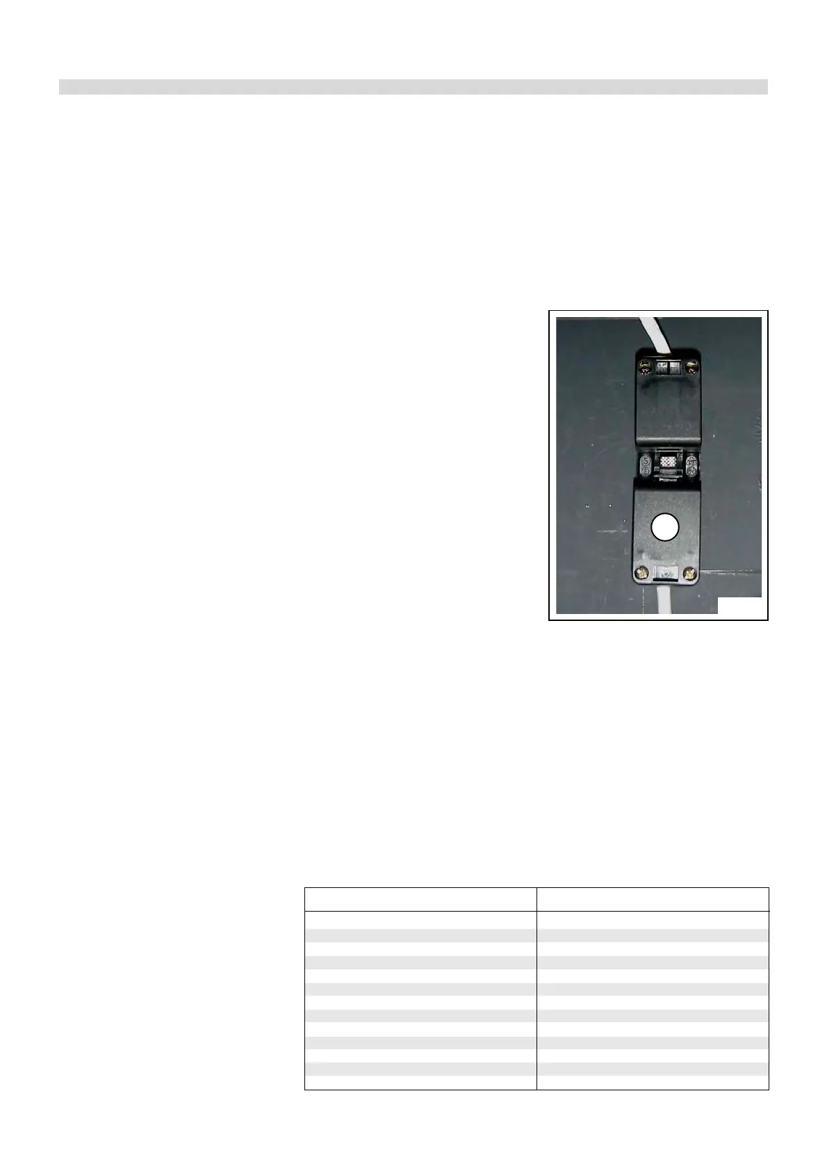
The boiler electrical supply (230 V – 50
Hz – single phase) is to be done direct-
ly on the three pole plug A (fig. 12) sup-
plied with the boiler. This boiler is phase
sensitive, it means that Phase and Neu-
tral wires from mains have to be con-
nected to Phase and Neutral terminals
of the three pole plug, otherwise the
boiler will go in lockout position.
It is necessary to fit a double pole switch
on the supply line in an easy accessi-
Fig. 12
A
ble position in order to make quick and
safe the service operations.
WARNING!
230 V cables shall be separated from
24 V ones, using the two plastic con-
duits supplied within the boiler casing
L.H. side panel.
Relationship between temperature (°C) and
nominal resistance (Ohm) of the sensors
NTC1 - NTC2 - NTC3
Example:
- At 25°C, resistance is
12000 Ohm
- At 90°C, resistance is
1300 Ohm
0 35400
10 22500
20 14700
25 12000
30 9835
40 6712
50 4672
60 3311
70 2388
80 1749
90 1300
100 980
110 749
Temperature (°C) resistance (Ohms)
TABLE OF RESISTANCE OF
NTC1 - NTC2 - NTC3