13
2.2.4.1 - MATERIALS FOR FLUE
PIPES
As material can be used the stainless
steel AISI 316 L or AISI 316 Ti, with a
minimum wall thickness of 0.4 mm, or the
aluminium, with a minimum wall thickness
of 1.5 mm, or the PVDF (Polyvinildi-
methylfluorure), or the PPS (Simple trans-
parent polypropylene), certified for this
use. Other materials and thicknesses are
also admitted, provided they guarantee at
least equivalent caracteristics.
In case of tubing of an existing chimney
the flue pipe has to be of aluminium (min.
thickeness of 1.5 mm) or of stainless
steel (min. thickness of 0,4 mm) and its
connections have to be water proof.
2.2.2 - BOILER LOCATION INSIDE A
BOILER HOUSE
Special attention shall be paid to local reg-
ulations and laws about boiler houses and
particularly to the obligation of keeping
minimum clearances and empty space
around the boiler. The installation shall be
in compliance with all latest regulations
and laws about boiler houses, installations
of heating and hot-water systems, venti-
lation, chimneys capable of evacuating
the flue gases of condensing boilers and
any other applicable requirement.
When selecting the position for the
installation of the boiler it has to be
considered that, for the cleaning and
washing operations of the boiler
body, one of the boiler sides must be
accessible for the removal of a spe-
cial baffle placed under the aluminum
sections.
The boiler can be put on a flat and suffi-
ciently strong base with the same di
mensions as the boiler ones and at le-
ast 100mm high (see fig. 5), in order to
assemble the condensate drain siphon.
An alternative to this base may be a
100 mm deep well next to the boiler as
siphon housing (see fig. 2). After instal-
lation the boiler shall be
perfectly horizontal and stable, to redu-
ce any possible vibrations or noises.
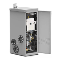
2.2.3 - BOILER CONNECTION
The boiler Modulex leaves the factory pre-
disposed for the hydraulic and gas con-
nection on the back side of the boiler. The
smoke outlet is placed on the back side
2.2.4 - CONNECTION TO THE
CHIMNEY
ATTENTION:
BEFORE ASSEMBLING THE CHIM-
NEY DUCT IT’S ABSOLUTELY NE-
CESSARY TO SET A SUPPORT UN-
DER THE SMOKE CHAMBER TERMI-
NAL
Into a condensing boiler, the smokes re-
ach a very low temperature (Max 84°C).
So, it’s necessary that the chimney is
perfectly impermeable to condensation of
combustion products and built with mate-
rials corrosion resistant.
The various spigot joints have to be well
sealed and endowed with provided for
gaskets, so that to prevent the conden-
sation spillage and the air entry.
For the chimney dimensioning, diameter
and height, it is necessary to make refe-
rence to the national and local regulations.
In order to avoid, during the operation, the
ice formation, the temperature of the insi-
de wall in every point of the system for
the combustion products evacuation, for
all of its length, doesn't have to be lower
than 0°C.
For operation in condensing conditions
with the outdoor temperature of project, it
will be therefore necessary the realiza-
tion of a system of confluent condensa-
tion drain, according to the installation
conditions, in the collection box of the
boiler or separated by it.
of the boiler for MODULEX 360; it's pla-
ced on the R.H. side of the boiler for MO-
DULEX 450 - 540 - 630.
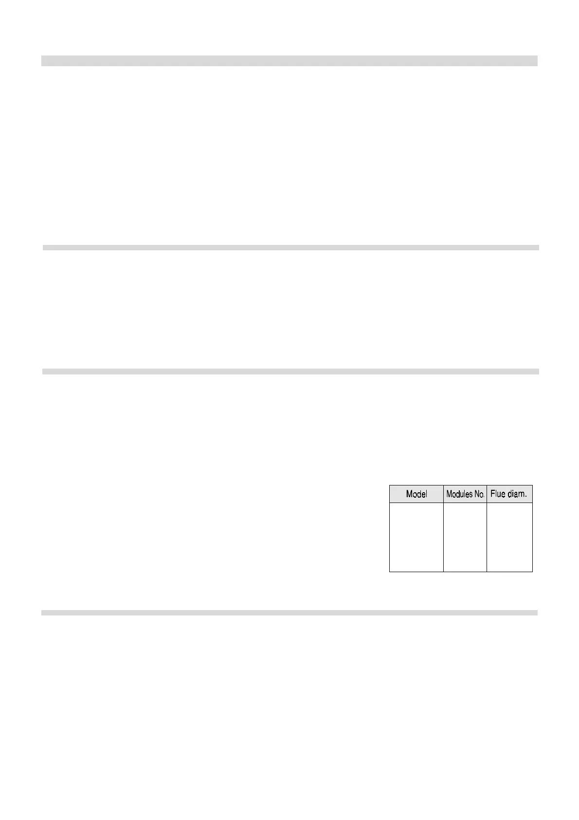
For the smoke chamber fixing, use the
4
5
6
7
450
540
630
360
250
250
300
300
screws and gaskets included into the in-
struction bag, and a cross screwdriver at
least 300 mm of length.