19
2.3.11 - MINIMUM WATER FLOW RATE
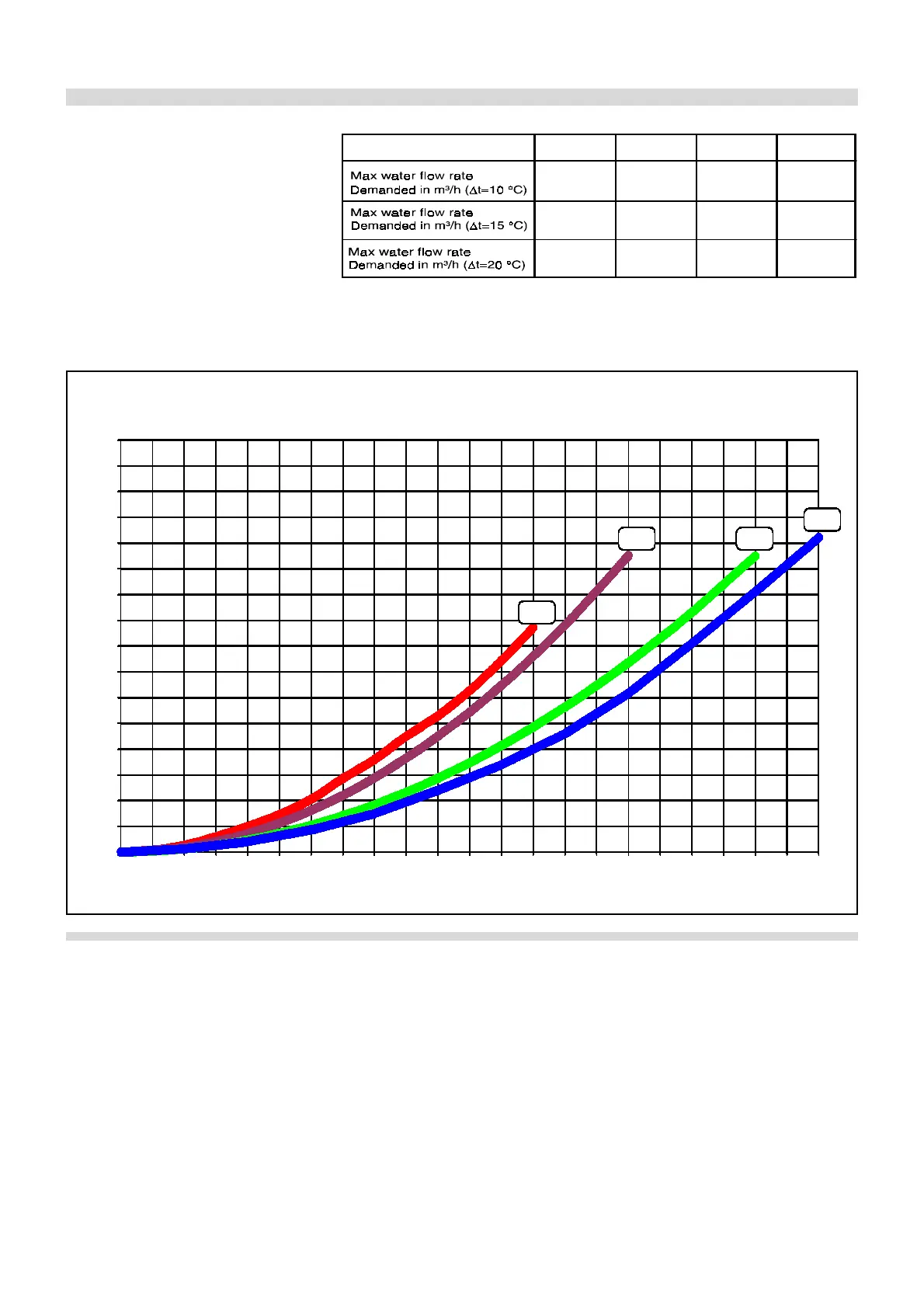
A minimum water flow rate, as shown in
the table on the right, is to be guaranteed
through the boiler at any time.
RICIRCULATION PUMP
The recirculation pump shall have a
manometric head able to assure the
water flow rate as per the diagram of fig.
8.
Pumps shall be calculated by install-
ers or technical engineers according
to boiler and system parameters.
fig. 8
The boiler consists of mutually connect-
ed combustion chambers; each of them
has its own burner, fan with air pres-
sure switch for control, two gas valves
with ignition and ionisation device.
Each group of these components is
called thermal element.
Max. output of a thermal element is 90 kW.
So, a 630 kW boiler consists of 7 thermal
elements.
Each thermal element has its own tem-
perature sensor NTC - Negative Temper-
ature Coefficient - called local NTC,
which locally checks the flow tempera-
2.4 - BOILER OPERATION
ture of each thermal element.
The flow temperature at the boiler outlet
and the return temperature at the boiler
inlet are controlled by global NTC tem-
perature sensors (see fig. 2).
In case of more heat request by heating
or DHW systems, the boiler starts up and
water will be heated by an aluminium boil-
er body. Then the boiler pump sends wa-
ter to the mixing bottle and from here to
the radiators, according to the heating
system choosen.
The combustion air is supplied by fans
and taken in from the boiler room. The
combustion air is then pushed into the
pre-combustion chamber through a dia-
phragm. Beyond the diaphragm, the air
mixes with gas and such mixture pass-
ing through the non-return valve is sent
to the burner. Then, on leaving the burner
surface, the air/gas mixture ignites elec-
trically and the resulting combustion gas-
es, after being transported (and cooled)
through finned tubes, enter the conden-
sate collecting manifold and then are
evacuated through the chimney.
The water side resistance curve of the
boiler is shown in fig. 8.
The pump is not an integral part of the
boiler.
0
0,5
1
1,5
2
2,5
3
3,5
4
4,5
5
5,5
6
6,5
7
7,5
8
02,5
5
7,5 10
12,5
15 17,5
20
22,5 25 27,5 30 32,5
35
37,5 40
42,5
45 47,5 50 52,5 55
PRESSURE LOSSES
(mH O)
2
360
450 540
630
WATER FLOW m³/h
WATER SIDE
PRESSURE LOSSES
kW output
360 450 540 630
30,96 38,70 46,44 54,18
20,64 25,80 30,96
36,12
15,48 19,35 23,22
27,09
It's recommended to choose a circu-
lator with the rate and discharge head
around 2/3 of its charactestic curve.