21
Fig. 9
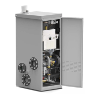
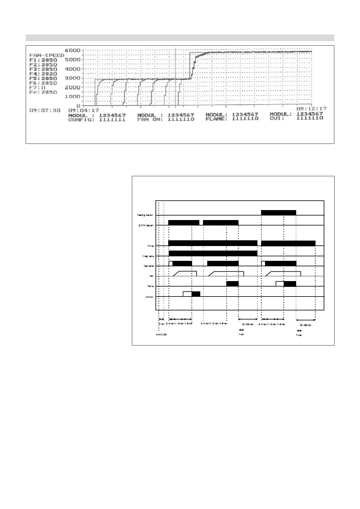
Ignition diagram, for Modulex 630, with 7 burners. (6 are working, 1 is during ignition procedure).
IGNITION SEQUENCE DIAGRAM
Fig. 9
2.4.2 IGNITION SEQUENCE
5 seconds after the switch ON-OFF is
ON, the pump is set up together, even-
tually, with the 3-way valve in the case
of a heat request from the Room Ther-
mostat. The ignition PCB (“CVI” means
Combined Valve and Ignition) is pow-
ered on and, after 24 sec, the fan is set in
motion and reaches the starting speed;
it stays in operation making the pre-
purge of the combustion chamber for
10 sec; in the meanwhile the air pres-
sure switch, actuated by the fan, switch-
es from C-NO (open position) to C-NC
(closed position) allowing the ignition
spark to be obtained and the gas valve
to be opened after 5 to 8 sec allowing
the AIR/GAS mixture. If within the safety
time there is no burner lighting the burn-
er is put definitely in lockout position (the
relevant red push button, on the front pan-
el board, will light).
When heating and/or DHW request ceas-
es, the pump stays in overrun according
to relevant pre-set times. Such sequence
is the same for the other burners without,
necessarily, keeping the lighting se-
quence in their assembling order, but in
their operation hours.