26
2.6.3 - ELECTRICAL CONNECTION
TO AN OUTER COMPENSA-
TOR, A ROOM THERMOSTAT
OR AN OUTER TEMPERATU-
RE SENSOR
Outer compensator: connect the com-
pensator 0-10V outlet signal to termi-
nals 9 - 10 of the 20-pole terminal-strip
(see fig. 16). By using this signal it is pos-
sible to set a global flow temperature de-
pending on the outdoor temperature.
ON/OFF room thermostat or program-
mer: it shall be connected to the termi-
nals 5-6 of the 20-pole terminal-strip (see
Fig. 16
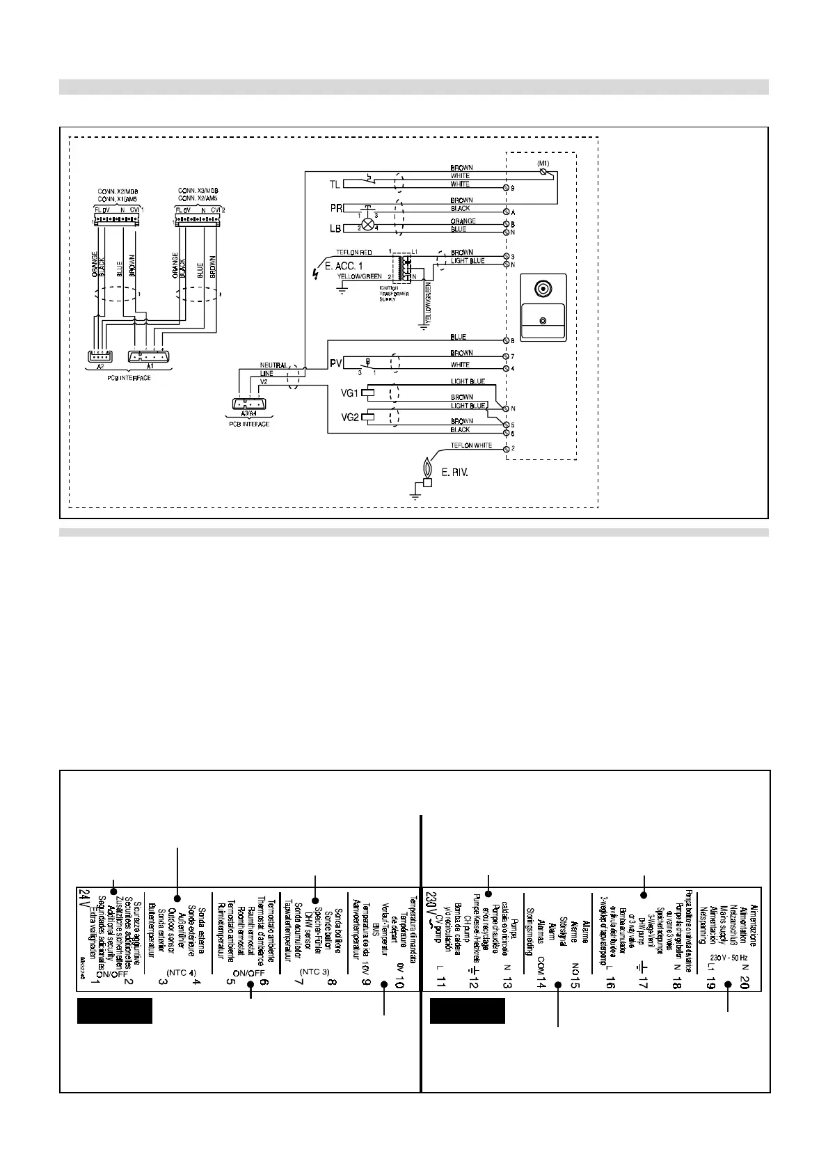
2.6.2 - WIRING CONNECTIONS OF THE IGNITION ELECTRONIC CARD
Fig. 15
E. ACC.Ignition electrode
E. RIV Ionisation electrode
PR Rest button (on main
board)
LB Lockout warning light
(on main board)
TL High limit thermostat
(local)
PV Fan air pressure
switch
fig. 16).
Outdoor sensor: supplied as standard,
it must be fitted on an outer wall exposed
to North or North-East, at a minimum
height from floor of 2.5 m. The mounting
in proximity of opening windows and
doors and ventilation grates has to be
avoided. Never fit the outdoor sensor in a
sunny position. It shall be connected to
terminals 3 - 4 of the 20-pole terminal-strip
(see fig. 16).
To avoid electromagnetic disturban-
ces it is necessary to separate the
external sensor wiring (between
sensor and terminal strip) from the
230 or 400 V harness (a plastic conduit
for 230 or 400 V harness and one for 24
V wiring)
Depending on the outdoor temperature
detected by the sensor the boiler will mod-
ulate and adjust the flow temperature ac-
cording to the programmed heating curve
(see fig. 19).
ON/OFF room thermostat in combina-
tion with outdoor sensor: When both
devices are connected as shown here
below, the boiler will modulate and ad-
just the flow temperature according to
the room and outdoor temperature detect-
ed by the two sensors (see fig. 19).
Note. The terminals 11 – 13 and 16 – 18 must be used to control a 3-way valve or a DHW tank loading pump or a boiler pump through
relays, as shown in the hydraulic schemas of fig. 6.1 to fig. 6.6. NEVER supply directly from these terminals the a.m. devices .
Connections detail
to the ignition electronic card
for each modul.
BMS
CONNECTION
STORAGE TANK
SENSOR OR
THERMOSTAT
ON-OFF
ROOM THERMOSTAT
AND/OR ON/OFF
TIMER
OUTSIDE
SENSOR
PRIMARY SYSTEM
PUMP
ALARM SIGNAL
(VOLT FREE CONTACT)
DHW PUMP OR
3-WAY VALVE
MAIN SUPPLY
FROM THE
FILTER
230 V24 V
ADDITIONAL
SECURITY
(LOW
WATER
PRESSURE)
The intervention of the
additional security
provokes the block of the
boiler and error code
is displayed.
E26