43
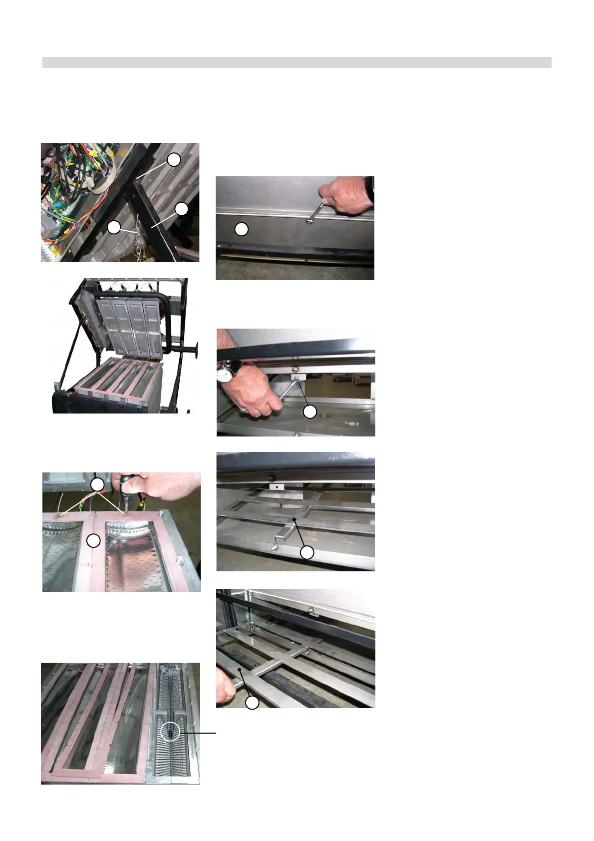
• Remove the burner gaskets “N”, remo-
ving the fixing screws “O”, and the bur-
ners.
The burner gaskets have to be repla-
ced every maintenance operation; they
have to be set between the burner and
the mixer, NOT BETWEEN THE BUR-
NER AND THE ALUMINIUM BODY!!
3
rd
phase – Cleaning
• Blow into the burners compressed air
from flame side (metallic spounge) to
the gas side (slick).
• Wash, with a water jet, the combustion
chamber: pay attention to not to wet
the electrical wiring. During this ope-
ration ascertain that the condensate
evacuation pipe is always free, so that
the water cannot come out from the
tray.
• Blow with compressed air in the com-
bustion chamber, in between the sec-
tions, so that all dirty parts are remo-
ved from the aluminum protrusions.
• Inspect the flue duct and the smoke
chamber.
N
O
4
th
phase – Reassembly
• Replace the burner sealing gaskets
• Proceed with the re-assembling fol-
lowing the same steps at the contrary.
Note: for the baffle “Q” setting into the
condensation collector, use the provi-
ded for sliding tracks.
• Before starting the boiler ascertain that
the condensate siphon is filled with
water.
• Before opening the gas feeding, che-
ck that the gas connection (previously
disconnected) is now correctly sealed.
To do this, open the gas cock and che-
ck the soundness of the coupling using
a soap solution.
• As soon as a burner is put into opera-
tion check immediately the soundness
between the gas valve and the rele-
vant premixing chamber.
• Make the combustion analysis and
check the combustion parameters..
• Make sure that all the gas pressure
test nipples, previously open, are clo-
sed and tight.
P
Q
R
R
L
M
H
• Remove the Ø 7 fixing screw “Q” of
baffle “R”
2
nd
phase
baffle removal
• Access to the condensation collector
by removing the Ø 10 screws of the
inspection flange “P”, on the opposite
side of the chimney connection.
• Set the support bar “L” in the provi-
ded for position on frame support “M”,
locking it with the spring “H”
• The boiler is open
BAFFLE POSITION
If removed or moved
during the boiler clean-
ing, it has to be set again
into the original position.