12 PG-E-Series | Version 2.15
Mounting and Set-up
f
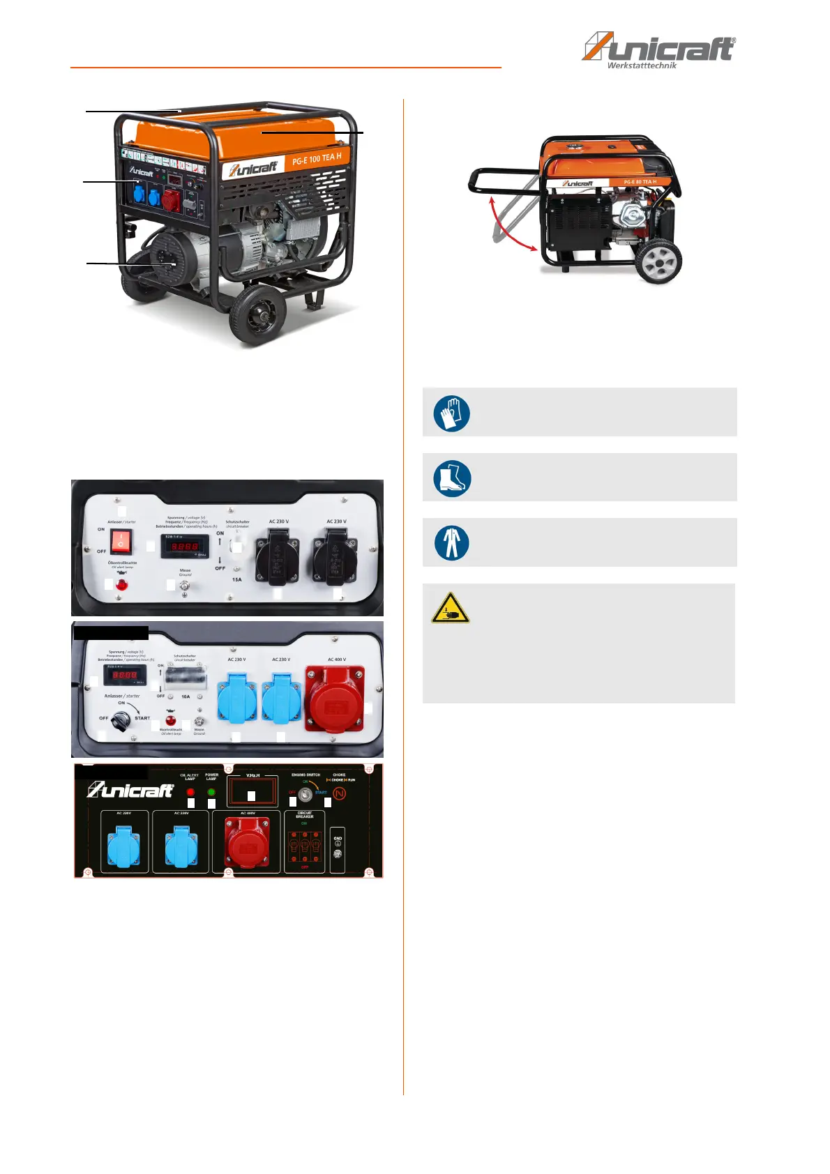
Fig. 5: PG-E 100 TEA H
1 Gasoline tank
3 Engine
4 Control panel
5 Frame
Fig. 6: Operating panel (PG-E 40, PG-E 80 TEA H, PG-E 100 TEA H)
1 ONN/OFF switch; Motor START switch
2 Display voltage, frequency, operating hours
3 Fuse switch
4 Oil control lamp
5 Ground connection
6 230 V-Consumer socket
7 400 V-Consumer socket
8 Choke
9 Operating lamp
Fig. 7: Fold-away transport handle
7 Mounting and Set-up
7.1 Unpacking
Step 1: Set the carton on the rigid, flat surface.
Step 2: Open the carton completely by cutting each cor-
ner from top to bottom.
Step 3: Leave the generator on carton to instal wheel kit.
Scope of delivery
- Wheels
- Handle
- Wheel axle
- Hardware bag; Including
1 - spark plug socket
1 - extension housing
- Instructions manual
1
5
8
PG-E 80 TEA H
6
7
6
3
5
9
4
2
1
8
PG-E 100 TEA H
Use suitable protective gloves!
Wear safety boots!
Wear protective clothes!
CAUTION!
Risk of crushing!
Injuries to hands and fingers may result from
improper use of the generator.
- Note the weight of the generator. Ensure stable
supports and support devices.