Mounting and Set-up
PG-E-Series | Version 2.15 13
7.2 Mounting
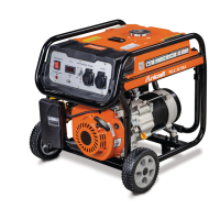
Mounting the wheels on:
- PG-E 30 SRA
- PG-E 40 SRA
- PG-E 60 SEA
- PG-E 80 TEA H
Step 1: Slide the axle through the frame brackets.
Step 2: Slide on the hub, wheel and flat washer, then in-
sert the cotter pin through the wheel axle hole.
Bend the cotter pin tabs outward to lock the pin
in place. (Fig. 8).
Mount the bumpers as shown in Fig. 8:
Step 3: Insert an M6 bolt through the rubber bumper and
insert an M8 bolt through the bottom of the bum-
per bracket. Secure the bolt with an M8 flange
nut.
Fig. 8: Mounting of the wheels and bumpers
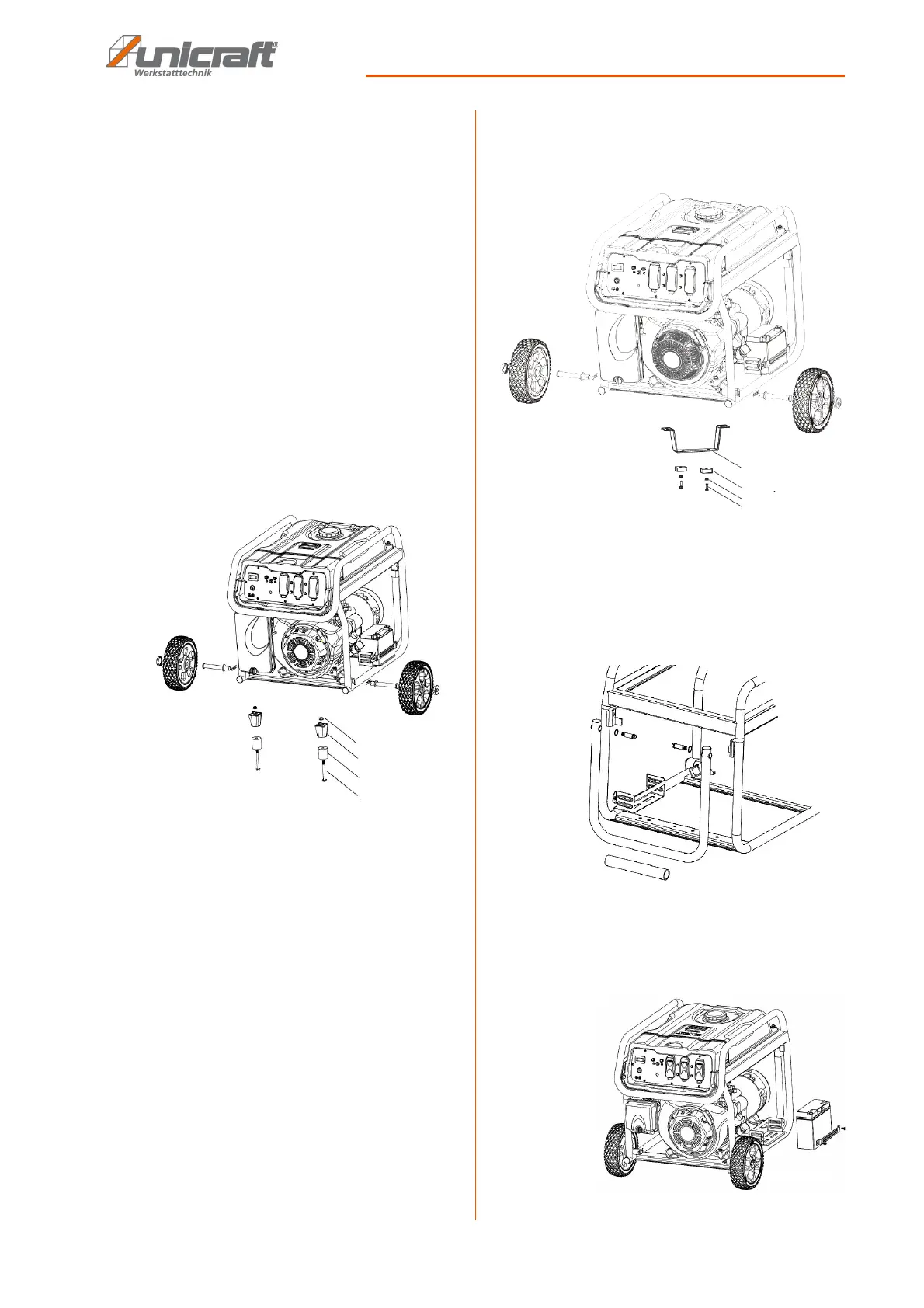
Mounting the wheels on:
- PG-E 90 SEA
Step 1: Slide the axle through the frame brackets.
Step 1: Slide the axle through the frame brackets.
Step 2: Slide on the hub, wheel and flat washer
Step 3: Insert the cotter pin through the wheel axle hole.
Step 4: Bend the cotter pin tabs outward to lock the pin in
place.
Mount the bumpers as shown in Fig. 9:
Step 5: Insert an M6 bolt through the rubber bumper and
insert an M8 bolt through the bottom of the bum-
per bracket. Secure the bolt with an M8 flange
nut.
Step 6: Install an M8 bolt through the generator frame
and through top of the bumper bracket.
Step 7: Secure the bolt with an M8 flange nut.
Fig. 9: Mounting of the wheels and bumpers
Install the handle assembly
Mount the handle as shown in Fig. 10: Insert the M8
bolts through the holes on the handle and the housing
holes and screw them to the housing with the nuts.
Fig. 10: Install the handle assembly
Mounting of the battery
Insert the battery into the holder and screw on the retai-
ning clip (Fig. 11).
Fig. 11: Mounting of the battery