A
Adam DunnAug 5, 2025
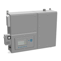
Why do my Union Instruments Measuring Instruments have unstable readings?
- RrdawsonAug 5, 2025
If your Union Instruments Measuring Instruments show unstable readings, it might be due to several factors. One cause is the pre-pressure regulator's inability to maintain constant pressure, requiring the installation of a sample gas pump. Direct sunlight causing rapid temperature fluctuations can also lead to instability, so avoid direct sunlight on the analyzer in unprotected installations. Also, air conditioning or heating units with large cooling capacity and control hysteresis can cause instability.