Installation Manual CWD 2005
___________________________________________________________________
28 Manual CWD2005.doc
4.4. Electrical power connection
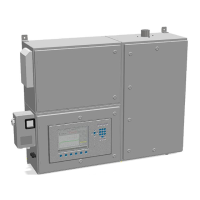
The line power supply electrical connections are wired to the terminal block in the
bottom section of the enclosure, see drawing figures 1 and 8. Check whether the
available voltage supply matches the analyzers rated voltage.
Figure 8: Connector block assembly
1 Power supply customer 2 Main switch: instrument on/off
3 Door safety switch 4 Line filter
5 Power supply 6 Ignition transformer
7 Door switch signal 8 Ignition impulse
9 Fan with power supply