Manual CWD 2005 Appendices
___________________________________________________________________
Manual CWD2005.doc 101
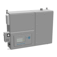
Figure 23: Filter unit with bypass valve
1. Filter 2. Ball valve
3. Ball valve 4. Ball valve
5. Indicator 6. Pre-pressure regulator (6 bar-18 mbar max.)
7. Holes for wall mounting
11.5. Gas connections
The CWD 2005 requires a very stable inlet pressure for correct operation and the
factory recommends the following pressure regulators.
A primary regulator is recommended together with a second regulator in front of the
CWD 2005 for pressures exceeding 6 bars. The second regulator has to be adjusted
at 18 30 mbar in accordance with the factory specification.
11.5.1. Adjust pressure regulator
The pressure regulator (6) is adjustable by the user and a small adjustment may be
necessary on the regulator(s) to allow the small specific gravity differential pressure
regulator (23) to operate within its correct input range. This facilitates any adjustment
to differential pressure as this controls the specific gravity sensor response speed.
11.5.2. Calibration gas connection
Connect the calibration gas using a high pressure dual stage gas regulator with high
pressure flexible metal hose and quick connections, a regulator for low pressure
output 18 mbar and a pressure gauge range 0 -
2
O (0-60 mbar).
The gauge in front of the CWD 2005 is necessary to show inlet pressure level.
Calibration gas is clean and a filter is not necessary.