Analyzer Overview Manual CWD 2005
___________________________________________________________________
20 Manual CWD2005.doc
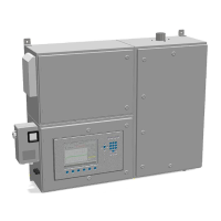
Figure 4: Enclosure shown from left hand side
1 Cable gland, signal 1 Cable gland power
3 Cable gland, signals 4 Cable gland, signals
5 Cable gland, signals 6 USB Connection
7 Interface connections 8 Fast loop
9 Carrier gas (SV.X11/3-4)* 10 Calibration gas 2 (SV. X14/3-4)*
11 Calibration gas (SV.X14/1-2) 12 Process gas (SV. X11/ 1-2)
The above drawing shows a standard instrument or instruments equipped with one
or two calibration gases or carrier gas. Instruments with the option of two process
gases have a different inlet arrangement and this will be labeled on the instrument.
not supplied as standard.