Tool flange
restriction
example
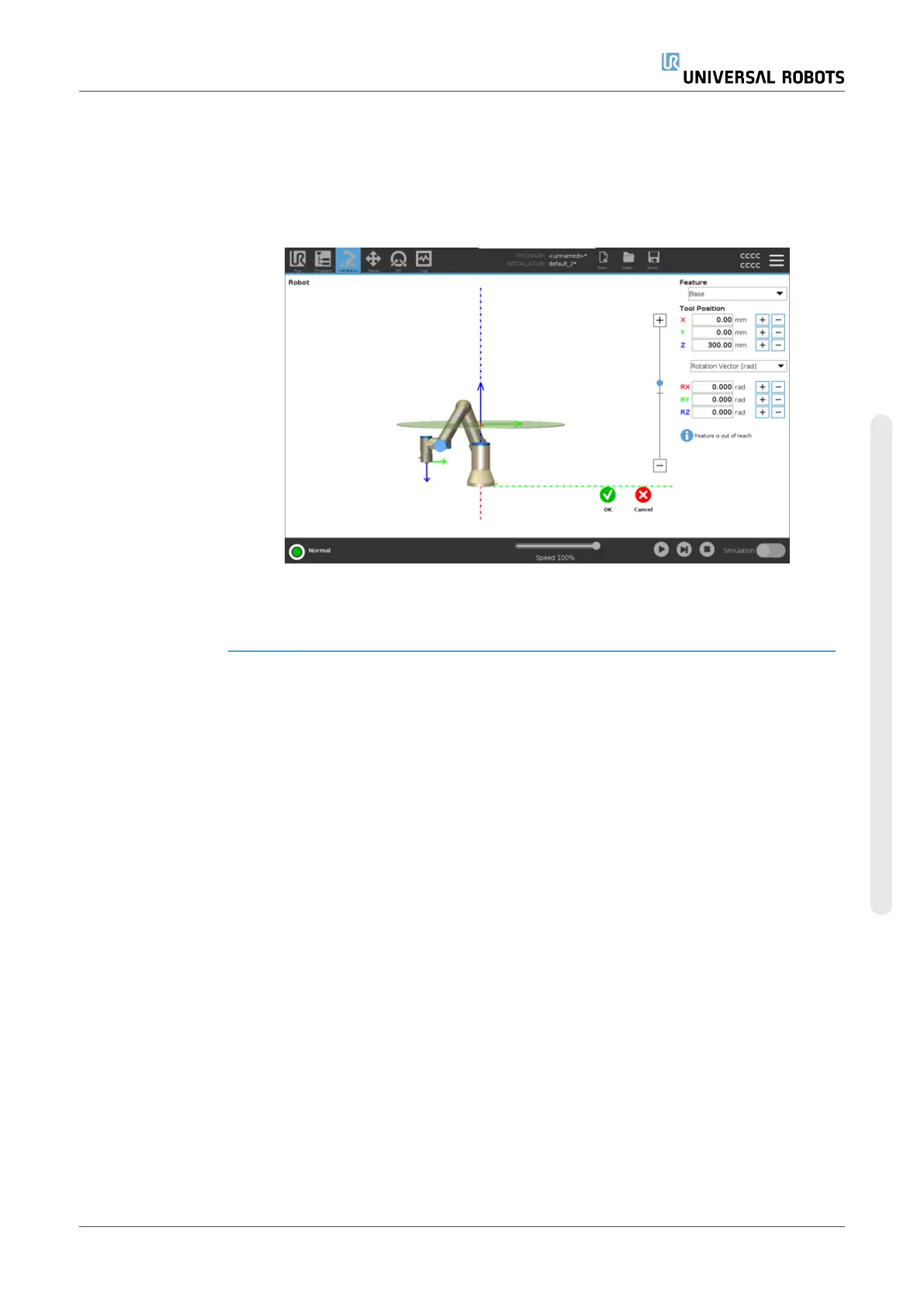
In this example, an X-Y-plane is created with an offset of 300mm along the positive Z-
axis with reference to the base feature.
The Z-axis of the plane can be thought of as “pointing” towards the restricted area.
If the safety plane is needed on e.g., the surface of a table, rotate the plane 3.142 rad or
180° around either the X- or Y-axis so the restricted area is under the table.
(TIP: Change the display of rotation from “Rotation Vector [rad]” to “RPY [°]”)
If needed it is possible to offset the plane in either positive or negative Z-direction later
in the safety settings.
When satisfied with the position of the plane, tap OK.
User Manual 159 UR10e
Copyright © 2009–2024 by UniversalRobotsA/S. All rights reserved.
 Loading...


