17.8.2. Tool Position Restriction
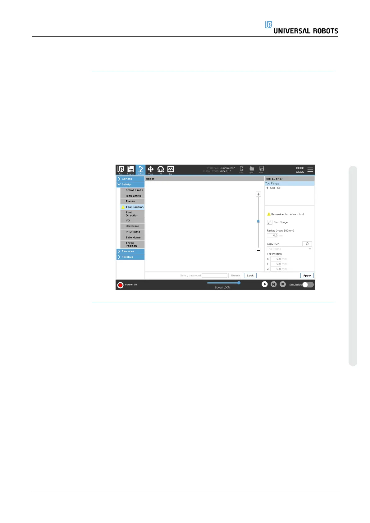
Description The Tool Position screen enables more controlled restriction of tools and/or
accessories placed on the end of the robot arm.
•
Robot is where you can visualize your modifications.
•
Tool is where you can define and configure a tool up to two tools.
•
Tool_1 is the default tool defined with values x=0.0, y= 0.0, z=0.0 and
radius=0.0. These values represent the robot tool flange.
Under Copy TCP, you can also select Tool Flange and cause the tool values to go
back to 0.
A default sphere is defined at the tool flange.
User Manual 163 UR10e
Copyright © 2009–2024 by UniversalRobotsA/S. All rights reserved.
 Loading...


