ENGINE
COOLING
CIRCUIT
RAW
WATER
COOLING
CIRCUIT
The raw water flow is created by a positive displacement
impeller pump. This pump draws water directly from the
ocean, lake, or river from a through-hull opening through a
hose to the water strainer. The raw water passes from the
strainer through the pump to a heat exchanger (through the
heat exchanger tubes) where it cools the engine's circulating
fresh water coolant. The raw water is then discharged into the
water injected exhaust elbow, mixing with, and cooling the
exhaust gasses. This mixture
of
exhaust gas and raw water is
driven through the stem tube and overboard.
Raw
Water
Pump
The raw water pump is a self-priming, rotary pump with a
non-ferrous housing and a neoprene impeller. The impeller
has flexible vanes which wipe against a curved cam plate
within the
impell~r
housing, producing the pumping action.
On no account should this pump be run dry
as
water acts as a
lubticant for the impeller. There should always be a spare
impeller and impeller cover gasket aboard (an impeller kit).
Raw water pump impeller failures occur when lubricant (raw
water)
is
not present during engine operation. Such failures
are not warrantable, and operators are cautioned to make sure
raw water flow is present at start-up.
Changing
the
Raw
Water
Impeller
1.
Close the raw water intake.
2. Remove the inlet and outlet port hoses from the pump,
noting the port location and positioning.
3.
Remove the pump assembly and its gasket from the
engine.
4.
Remove the three hex head screws that hold the housing
to the cover.
5.
Remove the impeller cover exposing the impeller.
6.
Pull the impeller off the shaft. Observe that the key on the
shaft is not lost.
·
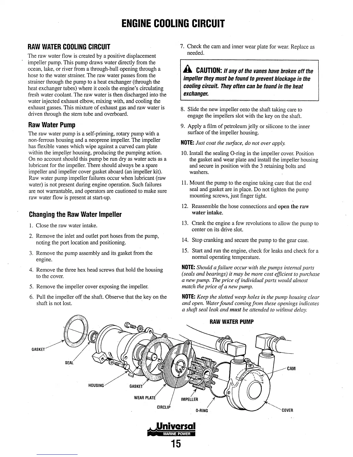
GASKET
HOUSING
WEAR
PlATE
7. Check the cam and inner wear plate for wear. Replace as
needed.
15
A
CAUTION:
If
any
of
the
vanes
have
broken
off
the
impeller
they
must
be
found
to
prevent
blockage
in
the
cooling
circuit.
They
often
can
be
found
in
the
heat
exchanger.
8. Slide the new impeller onto the shaft taking care to
engage the impellers slot with the key on the shaft.
9. Apply a film
of
petroleum jelly or silicone to the inner
surface
of
the impeller housing.
NOTE:
Just coat the surface, do not over apply.
10. Install the sealing
0-ring
in the impeller cover. Position
the gasket and wear plate and install the impeller housing
and secure in position with the 3 retaining bolts and
washers.
11.
Mount the pump to the engine taking care that the end
seal and gasket are in place.
Do
not tighten the pump
mounting screws,
just
finger tight.
12. Reassemble the hose connections and
open
the
raw
water
intake.
13. Crank the engine a few revolutions to allow the pump to
center on its drive slot.
14. Stop cranking and secure the pump to the gear case.
15. Start and run the engine, check for leaks and check for a
normal operating temperature.
NOTE:
Should a failure occur with the pumps intemal parts
(seals and bearings) it may be more cost efficient to purchase
a new pump. The price
of
individual pw1s would almost
match the price
of
a new pump.
NOTE:
Keep the slotted weep holes
in
the pump housing clear
and open. Water found coming from these openings indicates
a shaft seal leak and
must
be attended to wit/rout delay.
RAW
WATER
PUMP
0-RING