DC
ELECTRICAL
SYSTEM
DESCRIPTION
The charging system consists
of
an alternator with a mounted
voltage regulator, an engine
DC
wiring harness, a mounted
DC circuit breaker, and a battery and connection wires.
Because
of
the use
of
integrated circuits (IC's) the electronic
voltage regulator is very compact and is mounted internally
or
on
the back
of
the alternator.
Alternator
Troubleshooting
If
you suspect that the alternator is not producing enough
voltage to charge the engine's battery, check the following:
A
WARNING:
A
failetl
altematllr
can
become
very
bot.
Oo
not
touch
until
the
altematllr
bas
cooled
down.
D Make certain your alternator is securely mounted.
D Check the drive belts for proper tension.
D Inspect for loose
or
disconnected wires at the alternator.
NOTE:
An
isolator
with
a
diode,
a solenoid, or a battery
selector switch is
usutllly mounted
in
the circuit to isolate the
batteries so
the starting battery is not discharged along
with
the
house batteries.
If
the isolator is charging
the
starting
battery but not the house battery, the alternator is
OK and
the
problem is in the battery charging
circuit.
A
WARNING:
Shut
off
the
engine
battery
switch
or
disconnect
from
the
battery
when
working
on
the
engine
electrical
system.
Checking
for
Proper
Voltage
If
you suspect the alternator has failed perform the following
tests with the engine off:
1.
Using a voltmeter, connect the voltmeter red wire clip to
the output terminal B+.
2. Connect the voltmeter negative wire to any ground
on
the
engine.
3. Check the battery voltage.
It
should read 12 to
13
volts.
4. Check the voltage between the alternator ( +) positive ter-
minal B and any engine ground.
If
the circuit is good, the
voltage at the alternator should
be the same as the battery
(unless there's an isolator in the circuit, then the reading
would be zero).
A
CAUTION:
To
avoid
damage
to
the
battery
charging
circuit,
never
shut
off
the
engine
battery
switch
when
the
engine
is
running!
22
A
WARNING:
Before
starting
the
engine
make
certain
that
everyone
is
clear
of
moving
parts!
Keep
away
from
sheaves
and
belts
during
test
procetlures.
5.
Start the engine.
6.
The
voltage reading for a properly operating alternator
should be between 13.5 and 14.5 volts.
If
your alternator
is over-
or
undercharging, have it repaired at a reliable
service shop.
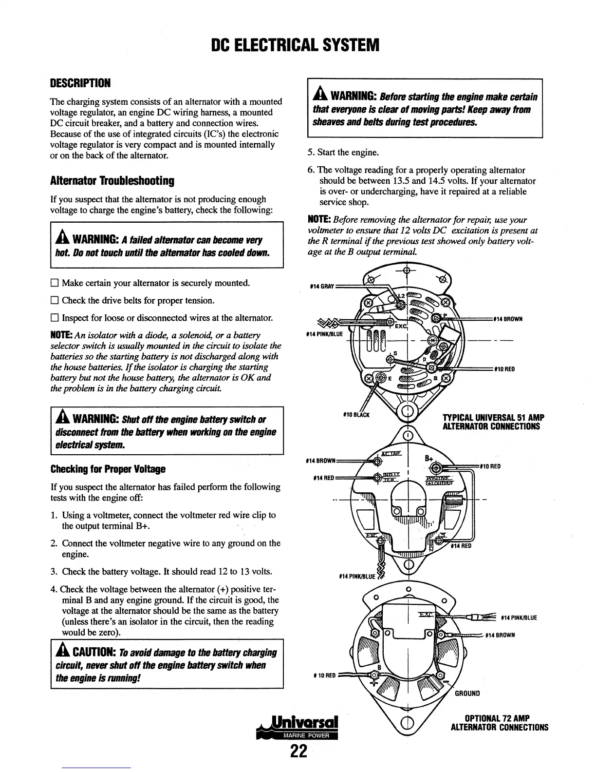
NOTE:
Before removing
the
alternator for
repair,
use your
voltmeter
to
ensure that 12 volts
DC
excitation is present at
the R terminal if the previous test showed only battery
volt-
age at
the
B output
terminaL
TYPICAL
UNIVERSAL
51
AMP
ALTERNATOR
CONNECTIONS
OPTIONAL
72
AMP
ALTERNATOR
CONNECTIONS