Installation Guide for Uplogix Local Managers 12
Connecting a power controller
Connect the power controller's serial port to port 1/6 on the Local Manager. A straight
Ethernet cable is typically used for this connection. However, some power controllers require
special cables. Consult your power controller documentation if a straight Ethernet cable does
not work.
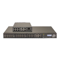
Connecting management Ethernet
To manage the Local Manager and attached devices in-band through the network, connect
Gigabit Ethernet port 0 (GE-0) on the front panel to your network using a straight Ethernet
cable. Both GE-0 and GE-1 auto negotiate their speed and duplex settings by default.
Alternatively, if your management network is fiber based, connect to the SFP in the option
slot. If GE-0 or GE-1 are connected to the network, they will take precedence over the fiber
connection.
When connected, secondary management Ethernet port GE-1 acts as a standby redundant
Ethernet management connection by default. GE-1 will become active if the GE-0 link drops.
Therefore, it is important that GE-0 and GE-1 be connected to switch ports in the same
network or VLAN.
Connecting devices to be managed
Connect the console ports of up to five devices to the five serial ports (1/1 through 1/5) on the
Local Manager. A straight Ethernet cable works for most devices, but some devices do require
a rolled cable or a cable with a non-standard pin out. Consult your managed device’s
documentation for console port serial setting and pin out information as necessary.
Note: If port 1/5 on your Local Manager is labeled as ‘1/5-DTE’, you will likely need to use a
rolled cable to connect this port to a managed device.