Installation Guide for Uplogix Local Managers 5
Installing the Uplogix 500 Local Manager
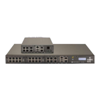
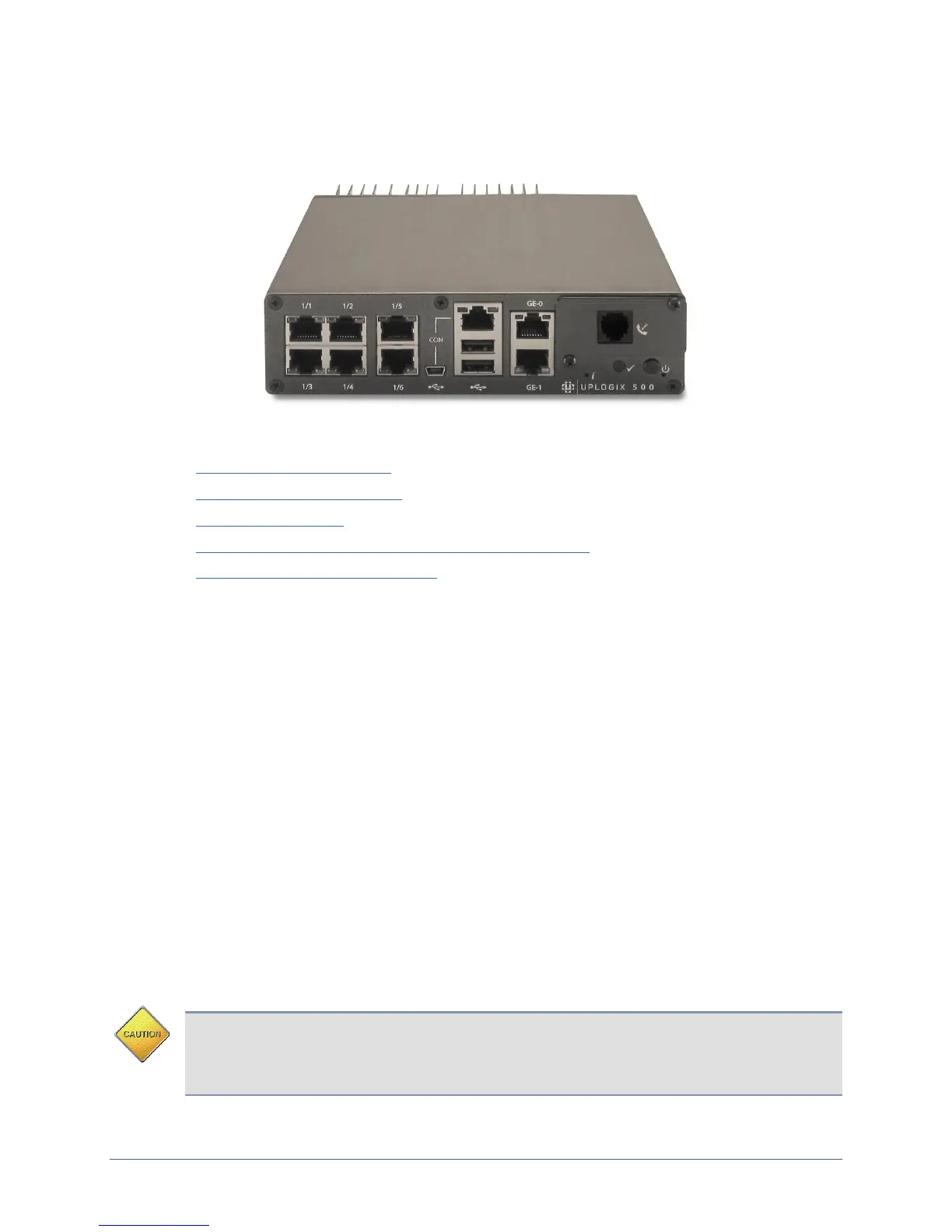
Uplogix 500
This section includes:
Unpacking the shipping box
Installing optional equipment
Installing the chassis
Making the connections required for initial configuration
Making the remaining connections
Unpacking the shipping box
Verify that you have received the following items:
Uplogix 500 Local Manager
1 Power supply and cord
1 mounting bracket
1 DB-9 to RJ-45 serial adaptor
Screws
Four clear rubber bumpers
Installing optional equipment
The Uplogix 500 supports field-installable modems, small form factor pluggable (SFP)
modules, and a temperature and humidity sensor. The Uplogix 500 also supports a 2-bracket
kit for center-mounting. Optional equipment may ship separately from the Local Manager.
Installing an Option Card in the Option Slot
The Local Manager supports five styles of equipment for installation in the option slot: V.92
modem, GPRS cellular modem, CDMA cellular modem, a DB-9 connection for an external
modem, and a SFP module to support a fiber connection.
Caution: To prevent equipment damage, do not connect the internal modem to digital PBX
systems, VoIP analog terminal adapters, or cellular modems. It is designed for use with
analog telephone lines only. Uplogix is not responsible for damage caused from attaching
the modem to a digital phone switch.