Installation Guide for Uplogix Local Managers 21
DC Model
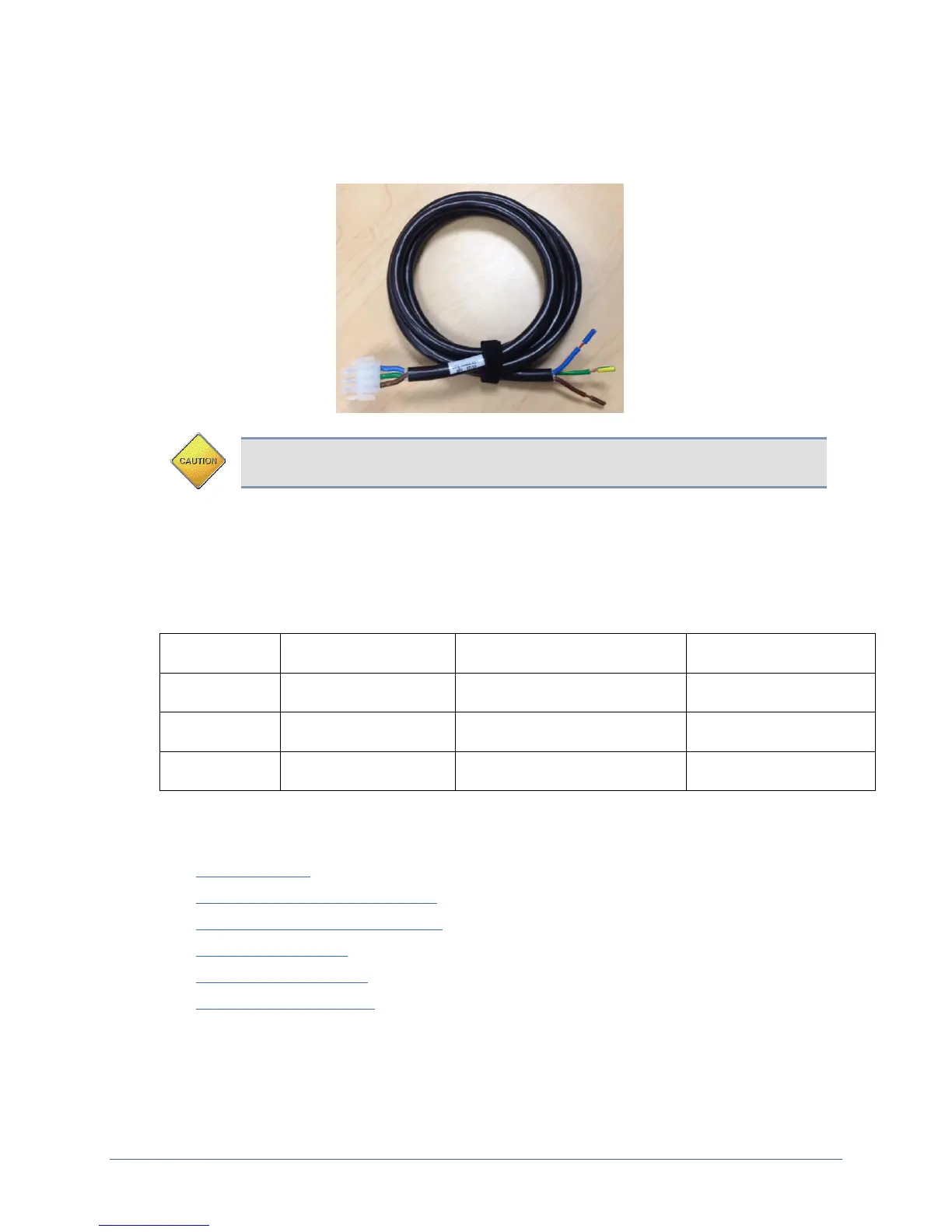
Available on the Uplogix 5000 only. The DC Uplogix Local Manager uses a power cord with a
Molex connector (part number: 39-01-4041) end and a three-wire split out.
Caution: Use the provided power cables to have an electrician connect the Local
Manager to the DC power source
Connect the green yellow wire to earth ground, connect the brown wire to positive voltage and
then connect the blue wire to power return. A dimly lit keypad and dark display indicates that
the unit has power applied. Power the unit on by pressing the middle keypad button. The
display on the front panel will illuminate and display progress messages as the device boots.
At the end of the boot sequence, it displays the message Uplogix status good.
Operating Voltage Range
(Referenced to Earth Ground)
Operating Voltage Range
(Referenced to Return)
Making the remaining connections
These connections are not required to complete the initial setup:
Power controller
Connecting management Ethernet
Connecting devices to be managed
Serial expansion card
Ethernet expansion card
Connecting a workstation
Connecting a power controller
Connect the power controller's serial port to port 1/6 on the Local Manager. A straight
Ethernet cable is typically used for this connection. However, some power controllers require