Page 12 Operator Manual
067903-004R1 LX Series Work Platform Fold Down Guardrails
F
OLD
D
OWN
G
UARDRAILS
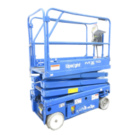
This procedure is only for passing through doorways. Guardrails must be returned to proper position
before using the machine.
Figure 9:
Fold Down Guardrails
F
OLD
D
OWN
P
ROCEDURE
NOTE:
When performing the following
procedures, retain all fasteners.
1. Place the controller on the plat-
form.
2. Starting at the slide-out deck:
• remove nuts, bolts and washers
from the top front corners of
guardrails (A)
• remove the nuts, bolts and wash-
ers from the slide-out deck side
guardrail midrails (B)
• remove nuts, bolts and washers
located at the top of the sockets
that hold the slide-out deck side
guardrails to the deck (C)
• fold the side guardrails down onto
the slide-out deck platform
• leave the end rail up and slide the
deck all the way in.
3. Go to the rear of the platform:
• close and latch the rear gate
• remove the nuts, bolts, washers, and corner brackets from the top of the rear guardrail
• fold the rear guardrail down onto the platform, being careful to keep the gate latched.
4. Unlatch the side gate so the left side guardrails can be folded down in two separate pieces. Also
remove the nuts, bolts and washers opposite the gate latch on the right side guardrail so it too can be
separated into two pieces (E).
5. Fold the rear half of the side guardrails onto the deck:
• lift up and fold down so the guardrails rest on the deck, on top of the rear guardrail.
6. Fold the front half of the side guardrails onto the deck:
• lift up and fold down so the guardrails rest on the slideout deck, with the guardrail posts resting in the
cutouts on the slideout deck toeboard (F).
7. Lift up and fold down the front slideout deck guardrail.
E
RECTION
P
ROCEDURE
1. Raise the front guardrail, making sure it is pushed down to secure the guardrail in the vertical position.
2. Raise the side guardrails, making sure each is pushed down to secure the guardrail in the vertical posi-
tion; align holes and install bolts, washers and nuts. Tighten securely.
3. Raise one of the slide-out deck side guardrail assemblies; align holes and install bolts, washers and
nuts. Tighten securely. Repeat this procedure for the other slide-out deck side guardrails.
4. Raise the rear guardrail, and install the corner brackets, nuts, bolts and washers.
5. Hang the controller from the front guardrail.
6. Before operating work platform check that all fasteners are in place and properly torqued.
WARNING
!
!
Before operating the machine, guardrails must be securely fastened in their erected position.
A
C
B
F
E
D
Operation 067903-004R1 LX Series Work Platform
Operator Manual Page 9
E
MERGENCY
L
OWERING
S
ERIAL
# 4022
TO
4274
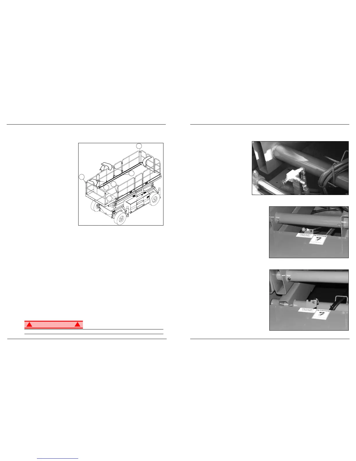
Figure 4:
The Emergency Lowering
Control is located at the rear
of the machine at the base of
the elevating assembly.
1. Open the Emergency Low-
ering Valve by pulling on
the knob and holding it.
2. Once the platform is fully
lowered, release the knob
to close the valve.
LX31
AND
LX41, S
ERIAL
# 4275
TO
C
URRENT
Figure 5:
Emergency Lowering Knob, LX31 and LX41
The Emergency Lowering Control Knob is
located at the rear of the machine at the
base of the elevating assembly.
1. Open the Emergency Lowering Valve by
pulling on the knob and holding it.
2. Once the platform is fully lowered,
release the knob to close the valve.
LX50, S
ERIAL
# 4275
TO
C
URRENT
Figure 6:
Emergency Lowering switch, LX50
The Emergency Lowering Control Switch is
located at the rear of the machine at the
base of the elevating assembly.
1. Open the Emergency Lowering Valve by
pusshing down on the toggle switch and
holding it.
2. Once the platform is fully lowered,
release the toggle switch to close the
valve.
 Loading...