Page 6 Operator Manual
067903-004R1 LX Series Work Platform Pre-Operation & Safety Inspection
NOTE:
If the engine is cold:
- on dual fuel models, hold the choke button in while starting the engine;
- on diesel models, depress the glow plug button and hold for 6 seconds to heat the glow plugs.
6. Position the Lift/Drive switch to the DRIVE position. The drive enable light should be ON.
7. With the speed range switch first in HIGH TORQUE and then in HIGH SPEED, depress the interlock
lever switch and slowly push the control lever to FORWARD then REVERSE positions to check for
speed and directional control. The farther you push or pull the control lever, the faster the machine will
travel.
8. Push steering switch RIGHT then LEFT to check for steering control.
9. Optional Outrigger Equipped Machines:
a. With the Lift/Outrigger/Drive switch in DRIVE, depress the interlock lever switch on the control lever
and position each Outrigger switch to the EXTEND position.
• Outriggers should be disabled. If an outrigger extends during this test
STOP
. Remove the
machine from service until it is repaired.
b. Turn the Drive/Outrigger/Lift switch to OUTRIGGER.
c. Depress the interlock lever switch on the control lever and position each Outrigger switch to the
EXTEND position to deploy all four (4) outriggers.
• Check the outrigger indicator lights; they should be ON.
NOTE:
When the platform is elevated 1 m (3 ft.) or higher the outrigger function should be disabled.
d. Depress the interlock lever switch on the control lever and position each Outrigger switch to the
RETRACT position.
• Partially retract all four (4) outriggers. The outrigger indicator lights should FLASH.
• Fully retract all four (4) outriggers. The outrigger indicator lights should be OFF.
10. Rehook the controller on the front guardrail.
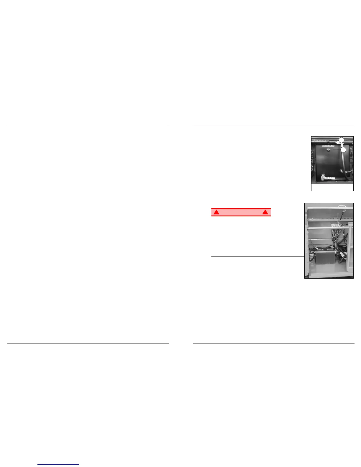
11. Open the Control Module covers to gain access to the chassis controls and tilt sensor.
12. Turn the Platform/Chassis switch to CHASSIS.
13. Push the throttle button in. Push the Raise button to elevate platform while pushing the tilt sensor off of
level. The platform should only partially elevate and the tilt alarm should sound. If the platform contin-
ues to elevate and/or there is no alarm,
STOP
and remove the machine from service until it is repaired.
14. Release the tilt sensor and fully elevate the platform.
15. Visually inspect the elevating assembly, lift cylinder, cables and hoses for damage or erratic operation.
Check for missing or loose parts.
16. Lower the platform partially by pushing in on the Lower button, and check operation of the audible low-
ering alarm.
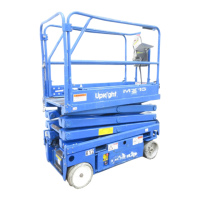
17. Open the chassis emergency lowering valve to check for proper operation by pulling and holding the
knob out (refer to “Emergency Lowering” on page 9). Once the platform is fully lowered, close the valve
by releasing the knob.
18. Turn the Platform/Chassis switch to PLATFORM.
19. Close and secure the module covers.
20. Enter the platform making sure the gate is latched.
21. Position the Lift/Drive switch to LIFT.
22. Depress the interlock lever switch and slowly push the control lever to UP to raise the platform; fully
actuate the control lever to check proportional lift speed. Slowly pull the control lever to the DOWN posi-
tion to lower the platform. Check that the lowering alarm sounds.
23. Optional Outrigger Equipped Machines:
a. With the Lift/Outrigger/Drive switch in LIFT, depress the interlock lever switch on the control lever and
position any outrigger switch to the EXTEND position.
• Outriggers should be disabled. If an outrigger extends during this test,
STOP
. Lower the platform
and remove the machine from service until it is repaired.
24. Turn the controller key switch to OFF, push the Emergency Stop button, and dismount the platform.
Hazard of explosive gas mixture. Keep sparks, flame, and smoking
material away from battery.
Always wear safety glasses when working with batteries.
Battery posts, terminals and related accessories contain lead and
lead compounds, chemicals known to the State of California to
cause cancer and reproductive harm.
Wash hands after handling.
Battery fluid is highly corrosive. Thoroughly rinse away any spilled
fluid with clean water.
Always replace batteries with UpRight batteries or manufacturer
approved replacements.
Check battery fluid level daily, especially if the work platform is
being used in a warm, dry climate.
If the electrolyte level is lower than 10 mm (
3/8 in.
) above plates,
add distilled water ONLY. Do not use tap water with high mineral
content; it will shorten battery life.
The battery and cables should be inspected regularly for signs of cracks in the case, electrolyte leakage
and corrosion of the terminals. Inspect the cables for worn spots or breaks in the insulation and for broken
cable terminals.
Refer to the Service Manual to extend battery life and for complete service instructions.
 Loading...