Page 14 Operator Manual
067903-004R1 LX Series Work Platform Maintenance
M
AINTENANCE
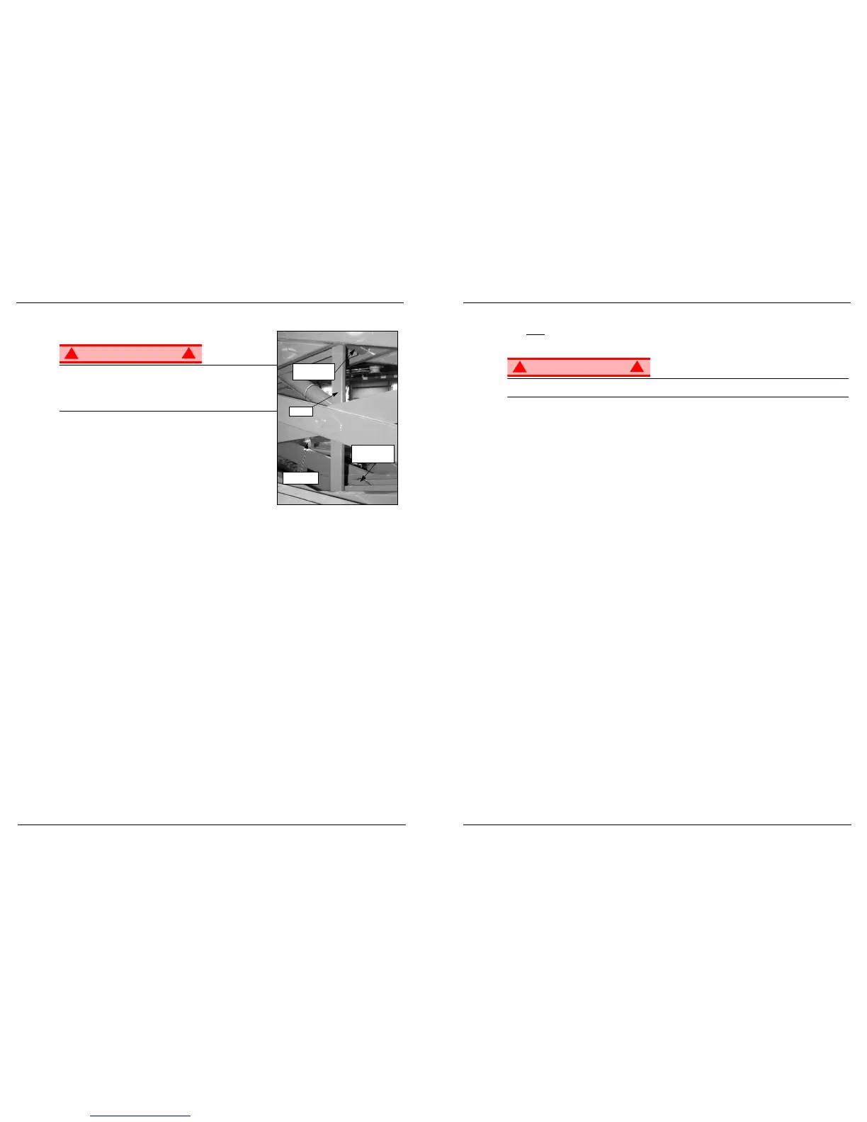
Figure 11:
Blocking Elevating Assembly
WARNING
!
!
Never perform service on the work platform in the elevating
assembly area while the platform is elevated without first blocking
the elevating assembly.
DO NOT
stand in elevating assembly area while deploying or
storing brace.
B
LOCKING
E
LEVATING
A
SSEMBLY
B
RACE
I
NSTALLATION
1. Park the work platform on firm, level ground.
2. Verify that the platform Emergency Stop button is ON.
3. Turn the Platform/Chassis switch to CHASSIS.
4. Start the engine, using the chassis controls.
5. Push the Throttle button in. The button will stay in and the engine speed will increase. Using the Raise
button, elevate the platform until the scissor brace can be rotated to the vertical position.
6. From the left side of the machine, disengage the locking pin securing the brace. Rotate the scissor
brace counterclockwise until it is vertical and between the two scissor center pivots.
7. Push the Lower button and gradually lower the platform until the brace is supporting the platform.
8. Disengage the throttle by pushing the Throttle button in again. The button will retract and the engine will
come to idle speed.
B
RACE
R
EMOVAL
1. Using the chassis controls, gradually raise the platform until the scissor brace clears the two scissor
center pivots.
2. Rotate the scissor brace clockwise until the locking pin engages.
3. Push the Lower button to completely lower the platform.
4. Make sure the Throttle button is disengaged and Platform/Chassis switch is on PLATFORM.
Never operate the work platform with the parking brakes released. Serious injury or damage could
result.
S
WITCHING
F
UELS
(D
UAL
F
UEL
O
NLY
)
1. With the engine running, turn the fuel selector switch (Figure 3: “Controls and Indicators,” on page 4) to
the center position.
2. After the engine has quit running, select the appropriate fuel supply.
3. Restart the engine.
T
RAVEL
WITH
P
LATFORM
L
OWERED
1. Verify the following:
• the chassis Emergency Stop button is in the ON position (pull out)
• the drive enable indicator is ON
• the Platform/Chassis switch is on PLATFORM.
NOTE:
If the drive enable indicator is OFF, verify that the platform is fully lowered and (if so equipped) the outriggers
are fully retracted.
2. After mounting the platform, close and latch the gate. Check that the guardrails are in position and prop-
erly assembled, with the fasteners properly torqued.
3. Check that the route is clear of persons, obstructions, holes and drop-offs, and is capable of supporting
the wheel loads.
4. Check clearances above, below and to the sides of the platform.
5. Pull the controller Emergency Stop button out to the ON position.
6. Turn the controller key switch fully clockwise to start the engine, releasing the key once the engine
starts.
NOTE:
If the engine is cold, on dual fuel models, depress and hold the choke button in while starting the engine. On
diesel models, hold the glow plug button in for 6 seconds to heat the glow plugs.
7. Set the Lift/Drive switch to DRIVE.
8. Set the speed range switch to HIGH TORQUE.
9. Grasp the control lever so that the interlock lever switch is depressed (releasing the interlock lever switch
cuts power to controller). Slowly push or pull the control lever to FORWARD or REVERSE to travel in the
desired direction. The farther you push or pull the control lever from center, the faster the machine will
travel.
10. While moving, push the speed range switch to HIGH SPEED for travel on level surfaces or to HIGH
TORQUE for climbing grades or traveling in confined areas.