Page 16 Operator Manual
067903-004R1 LX Series Work Platform Maintenance
E
NGINE
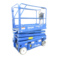
Figure 14:
Engine
C
OOLANT
The coolant recovery tank is mounted
on the inside of the door of the power
module.
1. Remove the cap on the coolant
recovery tank.
2. Add coolant to the “FULL” mark.
NOTE:
Never remove the radiator cap when
the engine is hot.
O
IL
The engine
must not be running
when you check and replenish the
engine oil. Refer to the Service Manual
to change the oil filter.
1. Remove the oil dipstick and check
the level indicator marks.
2. If the level is low, remove the oil filler cap.
3. Replenish with the proper engine oil (refer to the engine service manual that came with the machine).
CAUTION
!
!
DO NOT check coolant when engine or radiator is hot; hot coolant can cause severe burns.
F
UEL
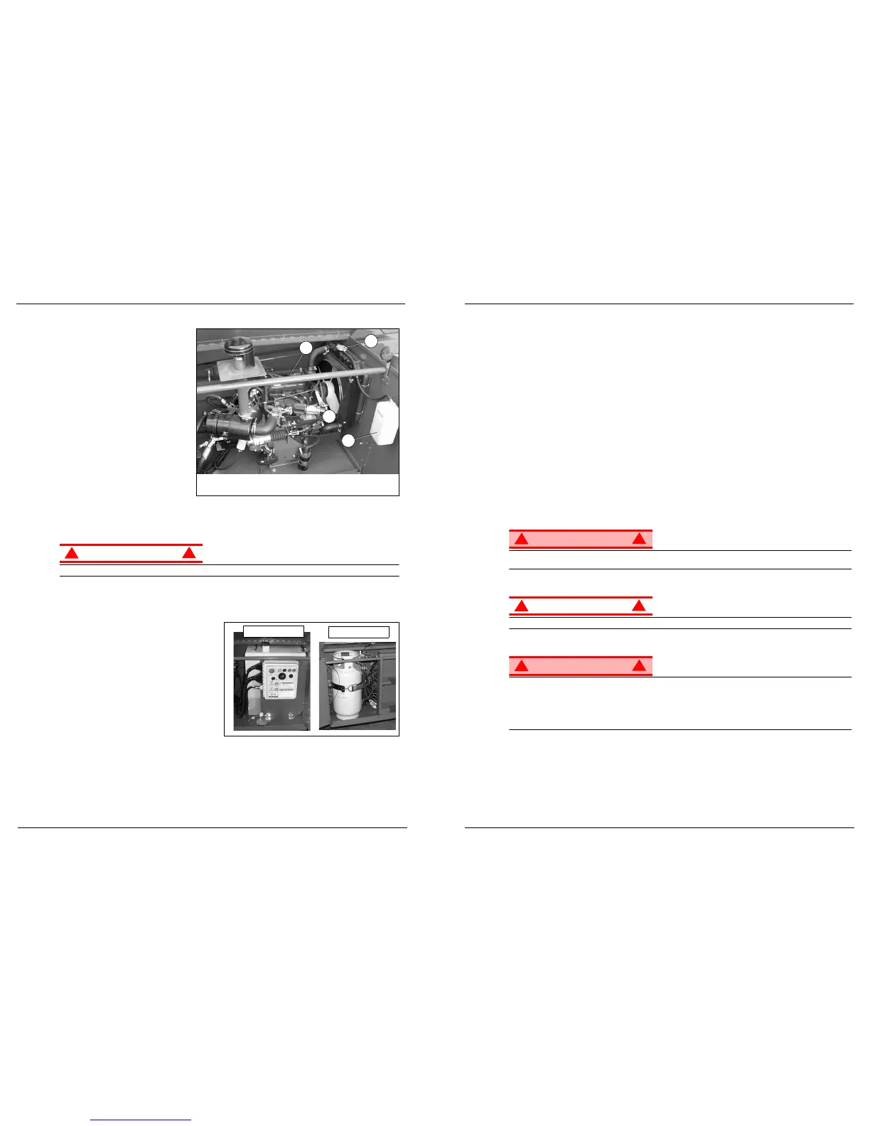
Figure 15:
Fuel Supply
D
IESEL
OR
G
ASOLINE
IMPORTANT: Fill with the correct fuel! Observe the
label near the fuel tank. It will say “Gasoline Only”
or “Diesel Only”.
The fuel tank for gasoline or diesel machines is
located in the Control Module, behind the chas-
sis controls. The tank is translucent. Check the
fuel level by observing the level of the liquid
through the tank.
P
ROPANE
(LP G
AS
)
The propane tank (dual fuel machines) is located in the Control Module to the left of the ladder, in front of
the battery.
3
4
1
2
1 Radiator Cap
2. Coolant Recovery Tank
3. Oil Filler Cap
4. Oil Dipstick
Propane (LP Gas)
Diesel or Gasoline
Pre-Operation & Safety Inspection 067903-004R1 LX Series Work Platform
Operator Manual Page 5
P
RE
-O
PERATION
& S
AFETY
I
NSPECTION
NOTE:
Carefully read, understand and follow all safety rules, operating instructions, labels and the Scaffold Industry
Association’s MANUAL OF RESPONSIBILITIES. Perform the following steps each day before use.
1. Open modules and inspect for damage, oil leaks or missing parts.
2. Check the hydraulic oil level sight gauge on the hydraulic tank with the platform fully lowered. Add fluid if
necessary.
3. Check that fluid level in the battery is correct (see “Battery Maintenance” on page 15).
4. Check the engine oil level and fuel level.
5. Check that all guardrails are in place, the slide-out deck extension is secured with the pin, and all fasten-
ers are properly tightened.
6. Check tire pressure: LX31 and LX41 - 3,4 bar (
50 psi
). The LX50 is equipped with poly-filled tires.
7. Carefully inspect the entire work platform for damage such as cracked welds in structural members,
loose or missing parts, oil leaks, damaged cables or hoses, loose connections and tire damage.
8. Carefully inspect the limit switches for signs of tampering.
9. Dual Fuel Models: set the dual fuel selector to the desired position. Set to the center position to purge
the system when switching fuels. If the machine is to be operated on propane, open the supply valve on
the tank
NOTE:
When using LP gas, use clean, water-free liquid petroleum gas, preferably from a bulk storage tank. Follow the
instructions located on the power module tray for filling the tank.
If you smell propane, close the supply valve on the tank immediately until you have located and
corrected the leak.
10. While the engine is cool, check the engine coolant level.
DO NOT check coolant when engine or radiator is hot; hot coolant can cause severe burns.
S
YSTEM
F
UNCTION
I
NSPECTION
STAND CLEAR
of the work platform while performing the following checks.
Before operating the work platform, survey the work area for surface hazards such as holes, drop-offs,
bumps and debris.
Check in
ALL
directions, including above the work platform, for obstructions and electrical conductors.
Protect control console cable from possible damage while performing checks.
1. Move the machine, if necessary, to an unobstructed area to allow for full elevation.
2. Place chassis and platform emergency stop switches in the ON position (Figure 3, Page 4) by pulling the
buttons out.
3. Verify that the platform/chassis switch is set to PLATFORM (Figure 3, Page 4).
4. Unhook the controller from the front guardrail. Firmly grasp the controller hanger in such a manner that
the interlock lever switch can be depressed, while performing the following checks from the ground.
5. Turn the controller key switch clockwise to ON. Turn fully clockwise to start the engine, releasing the key
once the engine starts.
 Loading...