Section 2 - Service and Repair Cylinders
107099-002 TM12 Work Platform Page 2-15
B
RAKE
C
YLINDER
The brake cylinder is located inside the right rear chassis wall above the wheel.
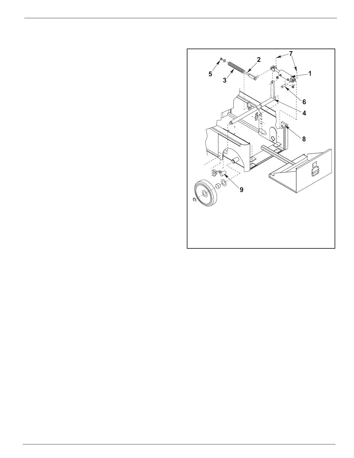
Figure 2-11:
Brake Cylinder, Remove & Replace
R
EMOVAL
1. Block the wheels to prevent the machine
from rolling when the brake is removed.
2. Use a 1000 Kg (
1 ton
) capacity jack to raise
the rear of the machine. Position blocks
under the machine to prevent it from falling if
the jack fails.
3. Block the front wheels to prevent the
machine from rolling.
4. Remove the spring compression nut and flat
washer from the tension bar.
5. Remove the retaining ring and right rear
wheel.
6. Remove the cotter pin and pivot pin from the
rear cylinder mount.
7. Remove the cotter pin from the tension bar
pivot allowing the cylinder to be lowered.
8. Disconnect the hose assemblies and cap
the openings to prevent foreign material
from entering.
9. Remove the cylinder from the chassis.
R
EPAIR
Refer to Cylinder Repair in Section 1 - General Information.
I
NSTALLATION
1. Connect the hose assemblies.
2. Install the tension bar pivot through the cylinder clevis and brake actuator and secure with a new cotter
pin.
3. Install the pivot pin through the cylinder mounting tabs and rear cylinder mount and secure with a new
cotter pin.
4. Install the wheel and retaining ring.
5. Install the flat washer and spring compression nut on the tension bar. Tighten the nut until at least flush
with the tension bar shaft or until the brake bar has full engagement with the tire.
6. Lower the machine and operate the drive circuit and check that the brake bars retract and clear the tires
when driving and fully engage the tires when stopped. Check for leaks
1. Brake Cylinder
2. Tension bar
3. Spring
4. Brake Actuator
5. Spring Compression Nut
6. Rear Cylinder Pivot Pin
7. Cotter Pin
8. Rear Cylinder Mount
9. Left Brake Bar