EasyManua.ls Logo

Usr USR-TCP232- E User Manual

Usr USR-TCP232- E
51 pages
To Next Page IconTo Next Page
To Previous Page IconTo Previous Page
Page #12 background imageLoading...
Page #12 background image
Multifunctional serial to Ethernet module user manual http://en.usr.cn
Jinan USR IOT Technology Co., Ltd tec@usr.cn
Page 12 /
/
/
/ 9
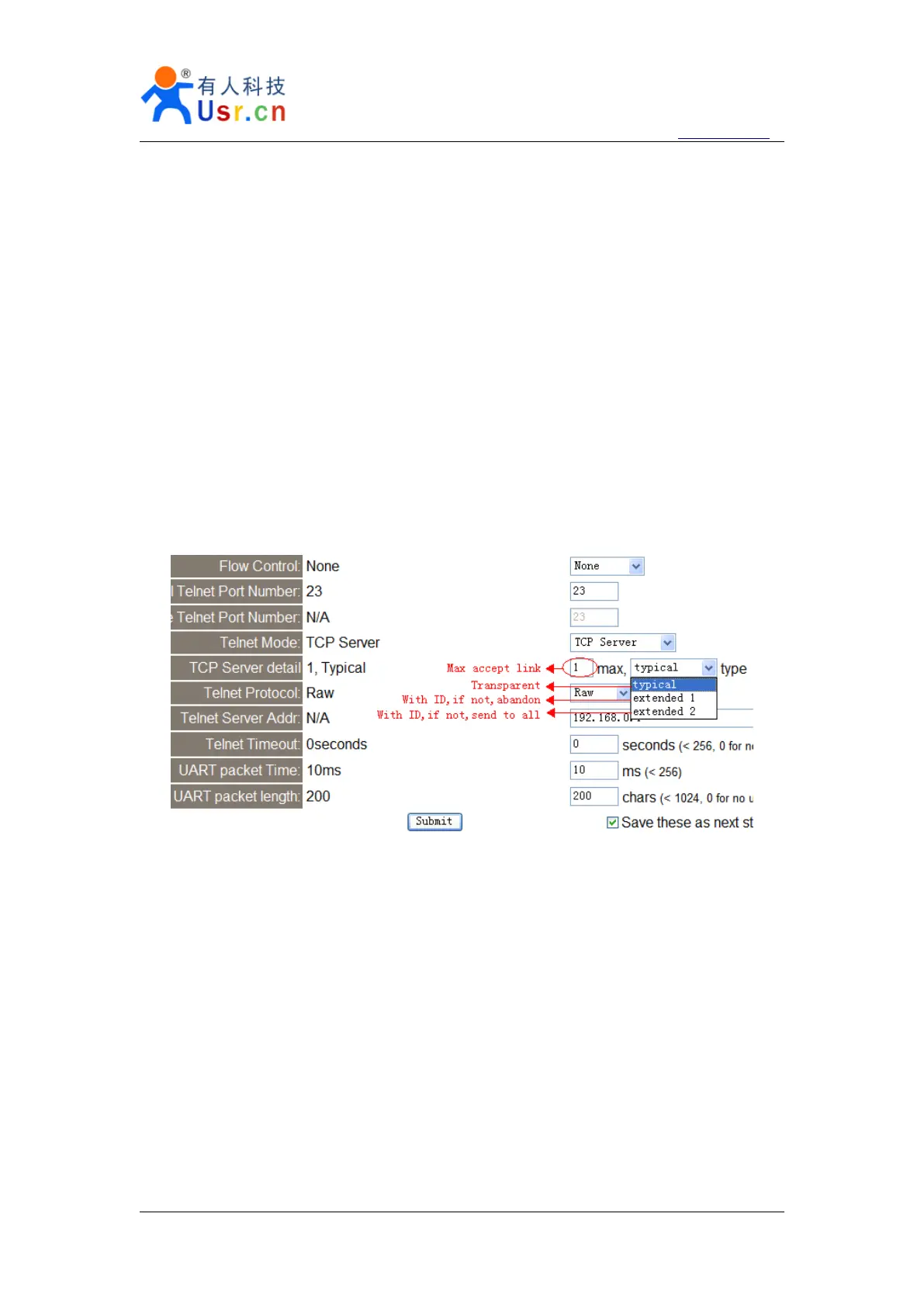
extend1, communicate with id, otherwise abandon;
extend2, communicate with id, otherwise send to all client.
For link type extended 1 and extended 2:
When receive data from ethernet, module will send data to serial port with head I
N
,followed by data. I
represent incoming data, N
represent client index.
When user MCU want send data to module serial port, start with head O
N
data... O
represent send out, N
represent which client.
When new TCP connection incoming, module will send C
N
M
to serial port, indicating
that there is current link N
accessed, total link number M .
When link number have exceed maximum, new link requirment will lead to message F
F .
When disconnect, module will send D
N
M , represent current link N is delete, left link
M.
Note:
serial data need to be sent in one package to module.
Diagram 2 - 8 web page configuration
2.6.
2.6.
2.6.
2.6. Httpd
Httpd
Httpd
Httpd Client
Client
Client
Client mode
mode
mode
mode
This function is easier used for web page developer. We establish one web server page, add
this:
[<?php echo $_GET['data']; ?>]
Means we can GET data from HTTP client
s request. Open this URL:
www.usr.cn/1.php?data=12345 , the web page is downbelow, we can see that the web server have
got the data(12345),
Question and Answer IconNeed help?

Do you have a question about the Usr USR-TCP232- E and is the answer not in the manual?

Usr USR-TCP232- E Specifications

General IconGeneral
InterfaceRS232
Power Supply5V DC
Storage Temperature-40°C to 85°C
Network Interface10/100Mbps Ethernet
ProtocolTCP/IP, UDP, HTTP
Humidity5% to 95% (non-condensing)
Baud Rate300bps~230.4Kbps

Summary

1. Introduction

1.1. Overview

General introduction to the serial to Ethernet adapter and its capabilities.

1.2 Features

Key functionalities, kernel, ports, modes, and protocols of the adapter.

1.3. Applications

Common use cases for the serial to Ethernet converter in various industries.

1.4. Electrical characteristics

Technical specifications for power supply, operating temperature, and current.

2. Work Mode

2.1. Block diagram

Illustrative diagram showing the module's application in a network setup.

2.2. UDP mode

Details on the UDP communication protocol mode, including data transfer.

2.3. TCP Client mode

Details on the TCP Client communication mode for establishing connections.

2.4. UDP Server mode

Details on the UDP Server communication mode for listening for data.

2.5. TCP Server mode

Details on the TCP Server communication mode for accepting client connections.

2.6. Httpd Client mode

Details on the HTTPD Client mode for web-based communication.

2.7. TCP Auto mode

Details on the TCP Auto mode combining Server and Client functionalities.

2.8. WEB to Serial mode

Details on the WEB to Serial mode for web page interaction.

3. Hardware interface

3.1. USR-TCP232-E

Hardware overview, power, LED status, and serial TTL interface for USR-TCP232-E.

3.2. USR-TCP232-ED

Hardware overview, power, LED status, and serial TTL interface for USR-TCP232-ED.

3.3. USR-TCP232-400

Hardware, power, LED, RS232, and RS485/RS422 interfaces for USR-TCP232-400.

3.4. USR-TCP232-401

Hardware, power, LED, and RS232 interfaces for USR-TCP232-401.

3.5. USR-TCP232-500

Hardware, power, LED, RS232, and RS485/RS422 interfaces for USR-TCP232-500.

3.6. USR-TCP232-504

Hardware, power, LED, and RS485 interfaces for USR-TCP232-504.

3.7. USR-TCP232-52E

Hardware, power, LED, RS232, RS485, and RJ45 interfaces for USR-TCP232-52E.

3.8. USR-TCP232-52PE

Hardware, power, LED, RS232, RS485, and RJ45 interfaces for USR-TCP232-52PE.

3.9. RJ45 Interface

Description of the RJ45 network port features and connectivity.

3.10. Reload

Instructions and button usage for restoring factory default settings.

5. Specific functions

5.1. Modbus RTU to Modbus TCP

Functionality for converting Modbus RTU protocol to Modbus TCP protocol.

5.2. Hardware flow control

Explanation of hardware flow control using RTS/CTS signals for RS232.

5.3. User MAC address

Procedure for setting, modifying, and saving the user MAC address.

5.4. Firmupdate

Detailed steps for updating the device firmware using the provided software.

6. Module USES

6.1. Hardware connection

Guide for connecting the module hardware, including evaluation boards and basic setup.

6.2. Login

Instructions for logging into the module's web interface for configuration and management.

6.3. Default working mode test

Procedure for testing the module's default operational mode and performance.

6.4. Common questions

Answers to frequently asked questions regarding module operation and troubleshooting.

6.4.1. Work across network segment

Troubleshooting communication issues when working across different network segments.

6.4.2. Ping is OK but can not open web pages

Troubleshooting web page access problems when ping command is successful.

6.4.3. After firm update, can not open web page

Troubleshooting web page access problems after a firmware update.

6.4.4. When connection established, server received serval chars

Troubleshooting issues related to received characters after a connection is established.

6.4.5. Every serval seconds, module reconnect

Troubleshooting frequent module reconnections, possibly related to timeouts.

7. Contact us

8. Modified history

Related product manuals