Wall Units
INSTALLATION INSTRUCTIONS
WWW.UTOPIAGROUP.COM
page 8
FITTING WALL CABINETS, DELUXE MIRROR UNITS,
DOUBLE FULL MIRROR UNITS, WALL CABINETS, OPEN
SHELF UNITS AND QUBE MIRROR CABINET
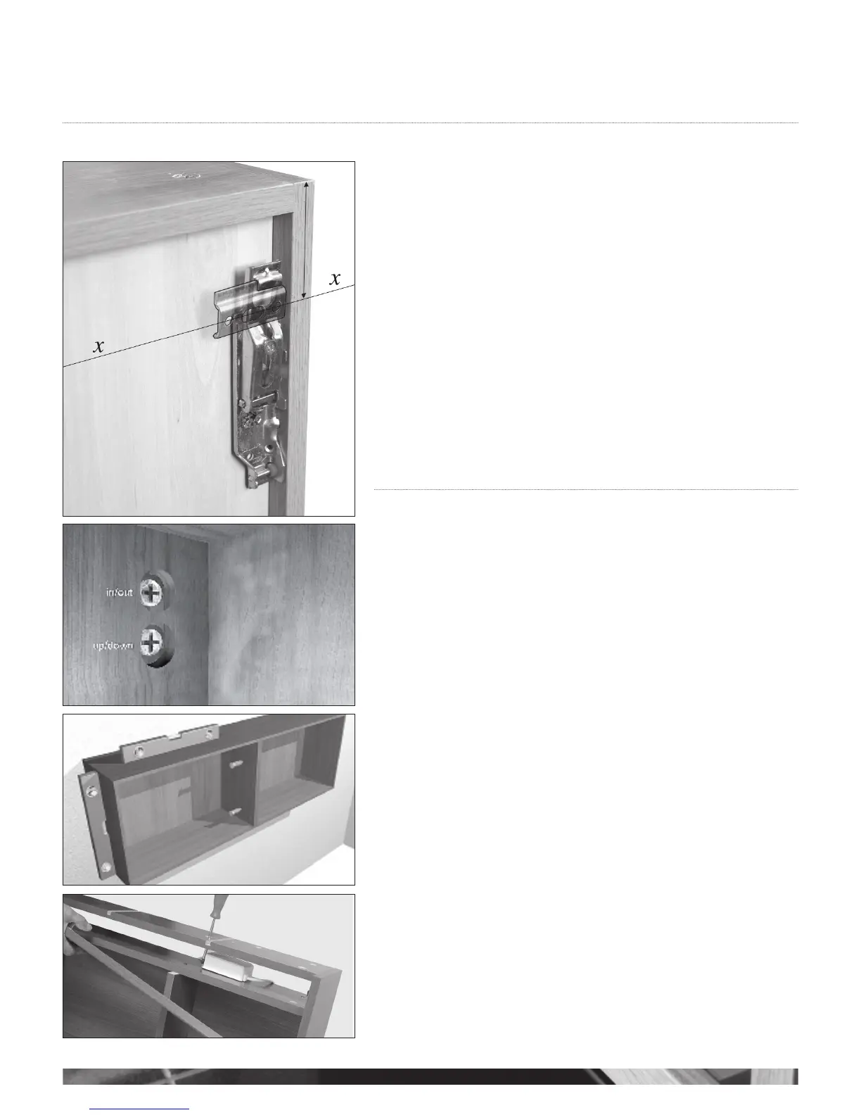
Wall cabinet hanging brackets are supplied with the unit.
It is advised that a line is drawn along the length of the wall, level with where the units are
to be fitted at the desired height above floor level. If tall units or tall sit on units are to be
used, these will determine the height of line x, i.e. the top of the unit being 1955mm if a
175mm plinth is to be used (see g 1).
If you are attaching this unit to a plasterboard wall please ensure that you use the correct
fixings.
The units then simply hook onto the wall fixed brackets. Adjust to gain a level top edge
using the adjustment screws - (see g 2). Also see instructions on page 4 (g 2. and 3).
A securing screw should be placed at the back of the unit to stabilise it. The screw should
be located through the fixed back rail at the back of the cabinet (see g 6 point A).
Once the units are in place they can be joined together (see g 3).
Once the unit has been levelled and pulled against the wall, fix conceal cover over
adjustment hole in back of unit with 10mm.
Cover caps supplied.
To fit mirror doors please refer to the section on fitting a mirror door on page 9.
FITTING THE LIGHTING UNIT
These units come with a transformer pre-installed that will power one extra light to the two
supplied with the unit, and the shaver socket.
If more than three lights are required, additional transformers must be added. These will fit
next to the existing transformer at the top of the unit, provided that the top of the unit is cut to
accommodate the transformer. Should the transformer be fitted with a 13 amp plug this must
be removed.
ACCESS AND REMOVAL OF TRANSFORMERS AND FRONT FASCIA
Carefully remove the fascia from the front of the unit and access the transformer
(see g 4).
Cabinet interior
g 1
g 3
TOP OF UNIT
g 4
g 2