10UV Smart D60 | Instructions for Use | Revision 1 US
Features
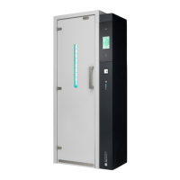
1. D60 unit
2. Disinfection area
3. Equipment holder
4. Wire holder
5. UV-C lamps (8x)
6. UV-C lamp protection covers (4x)
7. Door
8. Handle
9. Window
10. Control unit panel
11. Touch screen
12. Barcode scanner
13. RFID reader
14. Door magnets (2x)
15. Feet (6x)
16. Wall attachment
17. Control unit lock
18. Micro-switch
19. Main power supply inlet
20. Ethernet connector
21. Internal On/O-switch*
22. Foot pedal
Dimensions
a. Device height 2033mm
b. Device area (WxD) 861mm x 473mm
c. Disinfection area height 1750mm
d. Disinfection area (WxD) 384mm x 259mm
e. Maximum medical equipment insertion tube length 1200mm**
f. Maximum medical equipment wire length 2000mm**
* The D60 internal On/O-switch (21) is located behind the Control Unit panel (10). The Control Unit behind the panel shall only be accessed by UV Smart
qualied servicing personnel. Upon D60 installation at the client, the On/O-switch shall be switched On by the servicing personnel. Users can switch the
device On/O by plugging/unplugging the power cable into/from the wall socket.
**Geometry varies per equipment. Consult UV Smart or your local distributor in case of any questions.
6. Product overview
6.1. Packaging content
6.2. Features and dimensions
Items
- D60 medical device
- D60 Instructions for Use
- Power cable