ENGLISH
- 47 -
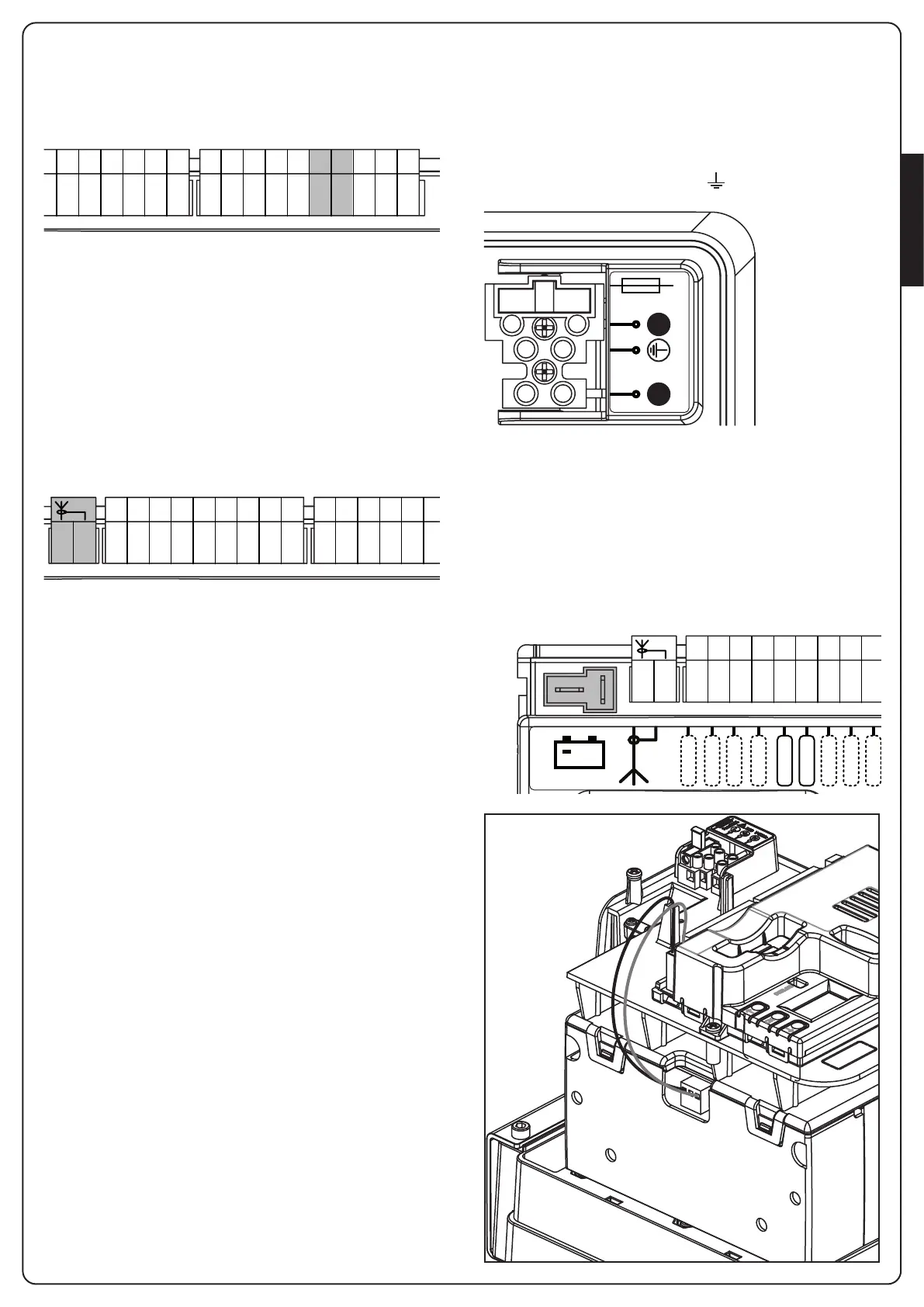
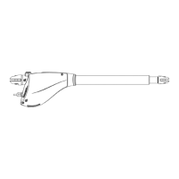
4.11 - LOCK
An electric lock can be assembled on the gate, to ensure a good
closing of doors. Make use of a 12V lock.
Connect lock cables to terminals K4 and K5 of the control unit.
K1
K2
K3
K4
K5
K6
K7
K8
K9
K10
J1
J2
J3
J4
J5
J6
J7
J8
J9
A1
A2
B1
B2
COURTESY
LIGHT
CONTACT
RECEIVER
LOCK
LAMP 24V-3W
+24VDC
COM (-)
+24VDC
(Photo TX / Edge Test)
START P.
STOP
COM
PHOTO
PHOTO-I
EDGE1
EDGE2
COM
BATTERY
+
START
ANT
M2
M1
Max 500mA
24 Vdc
POWER SUPPLY
24Vdc
24Vdc
Control unit model: PD12
4.12 - EXTERNAL AERIAL
We suggest to use the external aerial (model: ANS433) in order to
guarantee the maximal range.
Connect the antenna hot pole to terminal A2 (ANT) of the
control unit and the braiding to terminal A1 (ANT-).
NOTE: using the LUMOS flashing light with built-in antenna,
connect the terminal 3 of the flashing light to the terminal
A2 (ANT) of the control unit and the terminal 4 of the flashing
light to the terminal A1 (ANT-) of the control unit PD12
K6
K7
K8
K9
K10
J1
J2
J3
J4
J5
J6
J7
J8
J9
A1
A2
B1
B2
COURTESY
LIGHT
CONTACT
RECEIVER
LOCK
LAMP 24V-3W
+24VDC
COM (-)
+24VDC
(Photo TX / Edge Test)
START P.
STOP
COM
PHOTO
PHOTO-I
EDGE1
EDGE2
COM
BATTERY
+
START
ANT
M2
M1
Max 500mA
24 Vdc
POWER SUPPLY
24Vdc
24Vdc
Control unit model: PD12
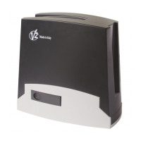
4.13 - PLUG IN RECEIVER
PD12 control unit is suitable for plugging in a MR2 receiver having
a high-sensitivity super-heterodyne architecture.
m WARNING: it is necessary to turn off the control unit
power before doing the operations mentioned here below.
Pay attention to the way you connect the removable
modules.
MR2 module receiver is provided with 4 channels and each of
them is suitable for a command of PD12 control unit:
• CHANNEL 1 g START
• CHANNEL 2 g PEDESTRIAN START
• CHANNEL 3 g STOP
• CHANNEL 4 g COURTESY LIGHT
NOTE: Before programming 4 channels and function
logics read carefully the instructions of MR2.
4.14 - ADI INTERFACE
The ADI (Additional Devices Interface) interface of the control unit
PD12 allows the connection to V2 optional modules.
Refer to V2 catalogue or to the technical sheets to see which
optional modules with ADI interface are available for this control
unit.
NOTE Please read the instructions of each single module to
install the optional modules.
4.15 - POWER SUPPLY
The control unit must be fed by a 230V 50Hz electric line,
protected by a differential magnetothermal switch complying with
the law provisions in force.
Connect the power supply wires to terminals L and N on the
board located next to the transformer.
Connect the earth cable to terminal
Fuse: 5A
L N
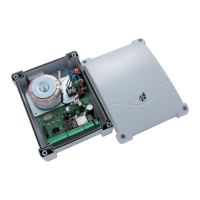
4.16 - BATTERY POWER
In the case of an electricity black-out, the device may be powered
using a battery pack (accessory code 161212).
The battery pack should be housed in the specific seating, as
shown in the figure.
Connect the battery pack connecter to the BATTERY terminals on
the control unit.
J2
J3
J4
J5
J6
J7
J8
J9
A1
A2
B1
B2
COURTESY
LIGHT
CONTACT
RECEIVER
LOCK
LAMP 24V-3W
+24VDC
COM (-)
+24VDC
(Photo TX / Edge Test)
START P.
STOP
COM
PHOTO
PHOTO-I
EDGE1
EDGE2
COM
BATTERY
+
ANT
M2
M1
Max 500mA
24 Vdc
POWER SUPPLY
24Vdc
24Vdc
Control unit model: PD12